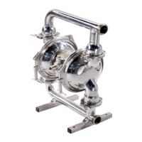
This document serves as the Service & Operating Manual for the N50 & X50 Hygienic B5005 Series Air Operated Double Diaphragm Pump, which is designed for lube-free operation and is Atex approved for use in potentially explosive atmospheres (Group II category 2). The manual provides comprehensive information for the installation, operation, maintenance, and troubleshooting of the pump, ensuring safe and efficient use.
Function Description
The N50 & X50 Hygienic B5005 Series pump is an air-operated double diaphragm pump with a 1:1 ratio design. Its primary function is to transfer fluids using compressed air to alternately pressurize the inner side of one diaphragm chamber while simultaneously exhausting the other. This action causes the diaphragms, connected by a common shaft, to move in a reciprocating motion. As one diaphragm performs a discharge stroke, the other is pulled to perform a suction stroke, maintaining continuous flow. The pump operates in a balanced condition during the discharge stroke, allowing it to handle significant discharge heads.
The alternating pressurization and exhausting of the diaphragm chambers are controlled by an externally mounted, pilot-operated, two-way distribution valve. This valve shifts to direct inlet pressure to one chamber and exhaust the other, then reverses to switch the pressure and exhaust paths. This spool movement is triggered by a pilot air pressure signal held against the diaphragm shaft, which is released when pilot holes in the diaphragm shaft align with the signal, causing a pressure imbalance that shifts the spool.
The pump's chambers are connected by manifolds equipped with suction and discharge ball valves for each chamber, ensuring unidirectional fluid flow. This design makes the pump suitable for handling a wide range of fluids, including those with high viscosity and specific gravity, and is particularly well-suited for hygienic applications due to its design and material compatibility.
Usage Features
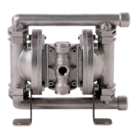
The N50 & X50 pump is designed for versatility and ease of use in various industrial settings, especially where hygiene and safety are paramount. It offers gentle pumping action, which is crucial for avoiding damage to food and beverage products. The pump supports a range of connection types, including RJT, DIN, FERULE, and SMS, allowing for flexible integration into existing systems.
A key feature is its self-priming capability, which simplifies the process of emptying containers. The pump is designed for lube-free operation as a standard, reducing maintenance requirements and preventing potential contamination from lubricants. It is compatible with food-grade elastomers like EPDM and PTFE, further enhancing its suitability for hygienic applications.
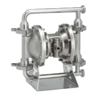
The pump can operate at pressures up to 8.6 bar and is capable of handling high viscosity and specific gravity fluids efficiently. It is certified CIP (Clean-In-Place) cleanable, which is essential for maintaining hygiene standards in sensitive industries. The pump also boasts EU Design approval and is constructed from 316L Stainless steel, ensuring durability and compliance with strict regulations. An optional pump stand allows for 180° rotation, providing flexibility in installation and maintenance.
For installation, the pump should be mounted in an upright position to ensure proper priming and operation. It is crucial to ensure all fluid connections are tight, using PTFE thread tape for leak-proof seals, as poor suction connection sealing can adversely affect performance. If pumping hazardous fluids or operating in an enclosed area, the exhaust must be piped to a safe location to prevent exposure to potentially harmful substances. The manual emphasizes that the pump delivers the same pressure at the discharge outlet as the air pressure applied at the air inlet, unless configured as a 2:1 ratio model. A pressure regulator should be installed if the air supply could exceed 125 psi.
Maintenance Features
The manual provides detailed instructions for maintaining the N50 & X50 pump, emphasizing the importance of regular checks and proper procedures to ensure longevity and optimal performance. Before any maintenance or repair, it is critical to shut off the compressed air line, bleed pressure, and disconnect the air line from the pump. The discharge line must also be bled of its pressure. Approved eye protection and protective clothing are mandatory when working on the pump.
Air Valve System Overhaul:
For pneumatic type air valve systems, maintenance involves removing the valve block, slide valve plate, and slide valve. All parts should be thoroughly cleaned and inspected for wear, replacing components as necessary. The contact faces of the slide valve and valve plate must be flat and free from scratches, with light polishing recommended if needed. If excessive wear is suspected in the valve block bore or valve carrier, these components should be removed and inspected, along with their O-rings. Cleaning with white spirits is recommended to remove oil films. The nominal diametrical clearance between the valve carrier and valve block bore should be maintained within 0.05-0.09mm; excessive clearance can cause erratic operation. A light grease should be applied to the valve block plug O-rings during re-assembly.
Wet-Side Overhaul:
Replacing ball valves involves removing the discharge and suction manifolds, along with the associated valve balls, seats, and O-rings. It is crucial to note the orientation of the valve seat relative to the valve ball, as incorrect positioning can lead to performance loss. All components should be cleaned, inspected for wear or damage, and replaced as needed. Ball or valve seat wear can result in loss of performance and suction lift. After re-assembly, manifolds should be torqued to specified settings.
Replacing Diaphragms:
This procedure requires removing both suction and discharge manifolds, including all ball valves, seats, and O-rings. The outer covers are then loosened and removed from the pump assembly, with their orientation noted for re-assembly. One frontplate is held in a vice (using soft jaws) or with an adjustable spanner, and the opposite frontplate is loosened and removed. The diaphragm, backplate, and bumpstop are then removed from the diaphragm shaft. The diaphragm shaft is carefully withdrawn from the center section.
Thorough cleaning and inspection of all parts for wear, damage, swelling, cracking, delamination, and chemical attack are essential, with replacements made as required. For rubber diaphragms, replacement is necessary if the fabric reinforcing is visible. For PTFE diaphragms, a light coating of grease should be applied to the back-up diaphragm before re-assembly. Before re-assembly, the diaphragm shaft seal and O-rings should be checked for wear or attack and replaced if necessary. Diaphragms are assembled onto the shaft in reverse sequence of removal, ensuring correct orientation (AIR SIDE molded onto one side, with the backplate adjacent to it). To achieve a leak-free seal around clamp bands, a plastic mallet should be used to gently tap the clamp band into position in a circular manner while simultaneously tightening the toggle bolt. Anti-seizure paste is recommended for stainless steel fasteners.
General Maintenance Advice:
The manual stresses that all BLAGDON PUMPS are lubricated with grease during assembly and do not require further lubrication. If oil use is unavoidable, a light No. 2 class lithium grease is recommended. If the pump accelerates or runs too fast due to lack of fluid, the air supply should be shut off immediately to prevent wear to elastomers. If the pumped fluid tends to dry up or set, the pump should be flushed as often as necessary and drained thoroughly before storage. Inverting the pump to drain fluid from non-return valves is also recommended.
Important Warnings and Safety Information:
The manual highlights several critical warnings. The pump is internally pressurized during operation, so all bolting must be in good condition and correctly reinstalled. Quick action/release connections are not recommended, and if used, levers must be locked. Before maintenance, all pressure must be vented from the pump and associated piping, and the air supply must be locked out. Approved eye protection and protective clothing are mandatory. Airborne particles and loud noise hazards necessitate ear and eye protection. Static sparking must be prevented, especially when handling flammable liquids, by grounding the pump, piping, valves, containers, and other equipment. For toxic or aggressive fluids, the pump must be flushed clean before disassembly, ensuring chemical compatibility and adherence to pressure/temperature limits. If the pump is unused for more than five days, care must be taken when restarting, and solidified deposits must be removed to prevent damage. Before operation, all gasketed fasteners should be inspected for looseness and re-torqued to prevent leakage. In cases of excess vibration, fitting a Pulsation Dampener is recommended, and flexible connections should be kept to a minimum length to avoid sharp flexing or straining.