Do you have a question about the BLAUBERG Turbo 100 and is the answer not in the manual?
Important safety advice before installation and operation.
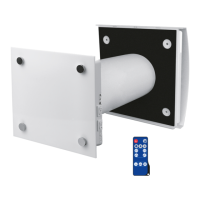
List of components included in the package.
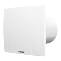
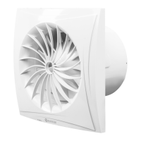
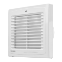
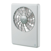
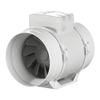
Overview of the mixed-flow inline fan and its capabilities.
Guidance on how to install the fan.
Explanation of connection terminals like L1, L2, QF, S, ST, X.
Details of the manufacturer's warranty terms and coverage.
Further details on consumer rights and warranty claims.
This document serves as a comprehensive user's manual for the Turbo series of inline mixed-flow fans, designed for technical, maintenance, and operating staff. It provides essential information regarding the fan's purpose, technical details, operating principles, design, and installation procedures for all modifications of the Turbo unit.
The Turbo series fans are mixed-flow inline ventilation units primarily intended for supply or extract ventilation in various premises. These fans are designed for direct connection to circular air ducts with diameters ranging from 100 mm to 315 mm. A key feature of these units is their two-speed motor, which allows for flexible air flow control to suit different ventilation requirements.
The functionality of the Turbo fans can be significantly enhanced and customized through various optional control features, denoted by specific suffixes in their model designation:
The fan's operational logic can further be categorized based on how it responds to temperature or timer controls:
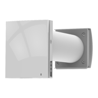
The Turbo fans are designed for continuous operation and offer versatile mounting options, suitable for horizontal or vertical installation on the floor, wall, or ceiling. They can be installed as standalone units or integrated into larger ventilation systems, either in parallel or in-series configurations. For horizontal mounting, a minimum 1-meter long air duct is recommended on the intake side. For vertical mounting, a hood should be used. The outlet spigot must always be connected to an air duct.
Safety is paramount during installation and operation. Only qualified electricians holding a work permit for electrical units up to 1000 V are authorized to perform installation and maintenance. It is crucial to disconnect the unit from the power supply before any connection, servicing, maintenance, or repair. The fan must be connected to the power mains through an automatic circuit breaker, with a minimum 3 mm gap between contacts on all poles. Before installation, the unit should be inspected for any visible damage to the impeller or casing, and the casing internals must be free of foreign objects. During mounting, care must be taken to avoid compressing the casing, as deformation can lead to motor jam and noisy operation.
The fan is designed to transport air within a temperature range of -25 °C to +60 °C (for 220-240/50 V models) or -25 °C to +40 °C (for 220/60 V models). The ambient air temperature for operation should be between +1 °C and +40 °C. The transported air must be free of dust, solid impurities, sticky substances, or fibrous materials. The unit is not suitable for use in hazardous or explosive environments containing spirits, gasoline, or insecticides. It is also important to ensure adequate air supply for combustion and exhaust in rooms with fuel-burning equipment to prevent back-drafting and the ingress of smoke or carbon monoxide.
The unit has an ingress protection rating of IPX4, indicating protection against splashing water. It is rated as a Class II electrical appliance. The arrow on the fan casing indicates the correct air direction in the system.
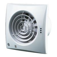
For models with a timer (Turbo XXX T), adjustment of the turn-off delay time is done by rotating a control knob. This adjustment must only be performed after disconnecting the fan from the power supply and using the specially designed plastic screwdriver provided, to prevent damage to the circuit board.
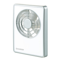
For models with electronic thermostats (Turbo XXX U/U1/U2(n)), the terminal box cover features two control knobs: one for setting the fan speed and another for setting the thermostat's temperature set point. An LED light on the fan casing indicates when the air temperature exceeds the set point. These knobs are rotated clockwise to increase values and counter-clockwise to decrease them.
Regular technical maintenance is essential to ensure the reliable operation and long service life of the Turbo fan. The fan surfaces should be cleaned from dirt and dust approximately once every six months. Before any maintenance operations, the unit must be disconnected from the power mains. To clean the fan, a soft cloth or a brush dampened with a mild detergent solution should be used. It is critical to prevent water or liquid from coming into contact with any electrical components. After cleaning, all surfaces must be wiped dry.
For storage, the unit should be kept in its original packaging box in a dry, closed, and ventilated area. The storage temperature should be between +5 °C and +40 °C, with a relative humidity not exceeding 70%. The storage environment must be free of aggressive vapors or chemical mixtures that could cause corrosion, insulation damage, or sealing deformation.
During handling and storage, appropriate hoist machinery should be used to prevent damage to the unit. All handling requirements specific to the type of cargo must be followed. The unit can be transported in its original packaging by any mode of transport, provided it is adequately protected against precipitation and mechanical damage. It must always be transported in its working position. Sharp blows, scratches, or rough handling during loading and unloading should be avoided. If the unit has been transported at low temperatures, it must be allowed to warm up to operating temperature for at least 3-4 hours before its initial power-up.
The manufacturer provides a five-year limited warranty, covering free replacement parts or a new unit from the date of purchase, provided a proof of purchase is supplied. The warranty does not cover damage resulting from misuse, neglect, shipping accidents, improper installation, voltage issues, unauthorized modifications, or exposure to corrosive conditions or weather. Warranty claims require the return of the defective parts or unit at the customer's cost.
| Power Consumption | 16 W |
|---|---|
| Voltage | 220-240 V |
| Frequency | 50/60 Hz |
| Duct Diameter | 100 mm |
| Impeller Material | Plastic |
| Housing Material | Plastic |
| Current | 0.1 A |
| Mounting | Wall/Ceiling |