Do you have a question about the Blink 6 Series and is the answer not in the manual?
Lists crucial electrical specifications and operational parameters for the charging stations.
Provides visual representations of how to connect the charging stations to various power sources.
Lists the electrical and mechanical tools needed for installation.
Details the specific parts provided by Blink Charging for the station, including pedestals and hardware.
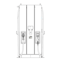
Displays dimensions and measurements for the dual pedestal charging station configuration.
Displays dimensions and measurements for the single pedestal charging station configuration.
Illustrates the wiring connections for dedicated power supply in a 240V single-phase setup.
Shows wiring for shared power in a 240V single-phase setup, highlighting connections.
Details the critical dimensions and hole specifications for the anchor plate.
Lists components of the anchor kit and instructions for fitting bolts to the anchor plate.
Provides steps and recommendations for installing the anchor plate when pouring new concrete.
Outlines the process for installing the anchor plate on existing concrete surfaces.
Details the steps for placing and securing the pedestal onto the installed anchor plate.
Instructions for preparing the head unit, including loosening screws and attaching cable racks.
Step-by-step guide for mounting the head unit onto the pedestal securely.
Guidelines on how to properly clean the charging station using safe methods.
Steps to follow to safely power up the charging station after installation.
Specifies the electrical and mechanical tools needed for wall/pole mounting.
Details the specific Blink Charging components for wall/pole mount installations.
Details critical dimensions for wall mounting, including clearances and heights.
Outlines the step-by-step process for installing the charging station on walls or poles.
Instructions for preparing the charging station head unit before mounting.
Steps for mounting the head unit onto the bracket or wall/pole assembly.
The provided document is an installation manual for the Blink Series 6 EV Charging Stations. This manual outlines the requirements, parts, and procedures for installing both single and dual pedestal mount, as well as wall/pole mount configurations of the charging stations.
The Blink Series 6 EV Charging Station is designed to provide electric vehicle charging capabilities. It is intended for installation on a dedicated electrical circuit and is capable of operating on either 240V or 208V circuits. The station is designed to draw a maximum of 30 Amps and requires three electrical supply wires (two hot, one ground, no neutral). All data communication for the station is wireless, relying on cellular communication, eliminating the need for data cabling. The manual emphasizes compliance with the National Electrical Code (NEC) or the Canadian Electrical Code (CEC) and recommends consulting a licensed contractor or electrician for installation.
The manual primarily focuses on installation rather than end-user features. However, it implies the following:
The manual includes instructions for cleaning the charging station:
| Brand | Blink |
|---|---|
| Model | 6 Series |
| Category | Battery Charger |
| Language | English |