EasyManua.ls Logo

Blooma Camden 350 User Manual

Blooma Camden 350
8 pages
To Next Page IconTo Next Page
Page #1 background imageLoading...
Page #1 background image
[01] x 1 [02] x 1 [03] x 1 [04] x 1 [05] x 1 [06] x 2 [07] x 1 [08] x 1 [09] x 1 [10] x 1 [11] x 1 [12] x 1 [13] x 1
[14] x 1 [15] x 1 [16] x 2 [17] x 1 [18] x 1 [19] x 1 [20] x 1 [21] x 1 [22] x 1 [23] x 2 [24] x 1 [25] x 1 [26] x 1
[27] x 1 [28] x 1 [29] x 1 [30] x 6 [31] x 1 [32] x 2 [33] x 2 [34] x 2 [41] x 1 [43] x 2 [44] x 1 [45] x 1
[46] x 2
01 02
GB IE
IMPORTANT - Whilst every care is taken in the manufacture of this product, care must be taken during assembly in case sharp
edges are present.
FR
IMPORTANT - malgré tout le soin apporté dans la fabrication de ce produit, il convient d’opérer avec précaution à cause de la
présence possible d’arêtes coupantes.
PL
Ważne - choć podczas produkcji urządzenia dołożono wszelkiej staranności, podczas montażu należy uważać na możliwe ostre
krawędzie.
RU
Важно - В то время как при изготовлении предпринимаются все меры безопасности, во время сборки также нужно быть
аккуратным, если есть острые углы.
ES
Importante - Si bien durante la fabricación de este producto se toman todas las medidas de cuidado necesarias, se debe tener
TR
Önemli - Bu ürünün üretimi sırasında her türlü önlem alınmış olmasına rağmen, montaj sırasında keskin kenarlara karşı dikkatli
olunmalıdır.
Camden 350
Byron G350
G46303 Version 3 - 2015
You will need - Vous aurez besoin de - Potrzeba
- Вам потребуется - Necesitará - İhtiyacınız
olacak
Tools not provided - Éléments non fournis -
Narzędzia nie dołączone - Инструменты не
предоставляются - Herramientas no incluidas
- Aletler verilmez
Assembly instructions - Instructions
de montage - Instrukcja montażu
- Инструкция по сборке - Montaj
talimatları
Barcode: 5052931254125 / 5052931254132
Code barre: 5052931249466 (Réf 641621)
Barcode: 2140002643633 (Ref 2000019846)
GB IE
FR
TR
KHK-WIN PID 63931 C7
[04] x 1
[31] x 1
[32] x 2
[33] x 2
[02] x 1
[03] x 1
[36] x 4
[04]
[33]
[32]
[32]
[33]
A
A
B
A
B
B
[02]
[46]
[46]
[03]
[36]
[36]
[36]
C
C
C
C
C
1 : 1 1 : 1
[35] x 4 (M6 x 60 mm)
[36] x 8 (M6 x 38 mm)
[37] x 10 (M6 x 13 mm)
[38] x 16 (M5 x 13 mm)
[39] x 6 (M4 x 10 mm)
[40] x 8 (M4 x 8 mm)
[42] x 2 (M3 x 10 mm)
[31]
AA
1.5V
[46] x 2
Question and Answer IconNeed help?

Do you have a question about the Blooma Camden 350 and is the answer not in the manual?

Blooma Camden 350 Specifications

General IconGeneral
BrandBlooma
ModelCamden 350
CategoryGrill
LanguageEnglish

Summary

General Safety and Assembly Precautions

Component Overview and Identification

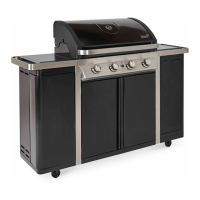
Identifies main components and parts required for assembly, referencing numbered items.

Main Body Assembly Steps

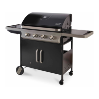
Illustrates the initial steps for assembling the main structure of the grill.

Assembling the Grill Base and Side Panels

Attaching the Base and Side Supports

Details the process of connecting the base frame and vertical side supports.

Installing the Rear Panel and Shelves

Describes how to attach the rear panel and integrate shelf components.

Installing Internal Components and Burner Assembly

Fitting the Drip Tray and Grate Support

Illustrates the installation of the drip collection tray and the primary grate support.

Connecting the Burner System

Details the steps for connecting the main burner tubes and associated components.

Attaching the Lid and Finalizing Exterior

Securing the Lid and Side Shelves

Instructions for attaching the main lid and final exterior side elements.

Gas Connection and Leak Testing

Guides for connecting the gas supply and performing essential leak checks for safety.

Assembly Verification and Main Structure Completion

Pre-Assembly Checks and Component Confirmation

Ensures all parts are present and correctly identified before proceeding with further assembly.

Assembling the Main Grill Body

Details the assembly of the central grill body structure using multiple components.

Attaching Internal Shelving and Supports

Shows how to install internal shelves and structural supports within the grill cabinet.

Cabinet Door and Side Panel Assembly

Installing Cabinet Door Hinges and Supports

Details the process of attaching hinges and supports for the cabinet doors.

Attaching Side Panels to the Main Body

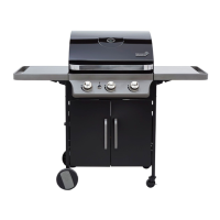
Illustrates connecting the side panels to the primary grill structure.

Fitting Cabinet Door Frames

Describes how to attach the frames for the cabinet doors.

Installing Door Handles or Knobs

Shows the installation of handles or knobs onto the cabinet doors.

Finalizing Side Cabinet Assembly

Completes the assembly of the side cabinet sections.

Attaching Cabinet Doors

Guides for mounting the assembled cabinet doors onto the grill.

Shelf Installation and Ignition System Setup

Installing Lower and Middle Shelves

Instructions for fitting the lower and middle shelves into the grill cabinet.

Installing the Warming Rack

Details the process of installing the warming rack.

Installing the Ignition Battery

Guides the user on how to install the battery for the electronic ignition system.

Connecting Ignitor Wires

Illustrates the proper connection of wires for the electronic ignition system.

Final Ignitor System Connections

Completes the wiring and setup for the grill's electronic ignition.

Final Assembly and Pre-Use Checks

Attaching Side Tables and Components

Illustrates the attachment of external side tables and other final components.

Connecting the Gas Supply

Provides instructions for safely connecting the gas cylinder to the grill.

Final Checks and Safety Assurance

Details important final checks, including leak testing and safety guidelines before operation.

Related product manuals