4.3.3 Earphone Circuit
An earphone insert into the phone, right audio channel was from high level pull to low, take
interrupt to CPU, so CPU “knew” the earphone was plugged in, then display “earphone
plugged in”, this is earphone detect process. Earphone pull out is adverse process.
After ear phone plugged in, MIC power supply will be turn on, so CPU read ADC2_MIC’s
ADC value to check if earphone key was pressed. If earphone key was pressed, the ADC
value was at low level, otherwise was high.
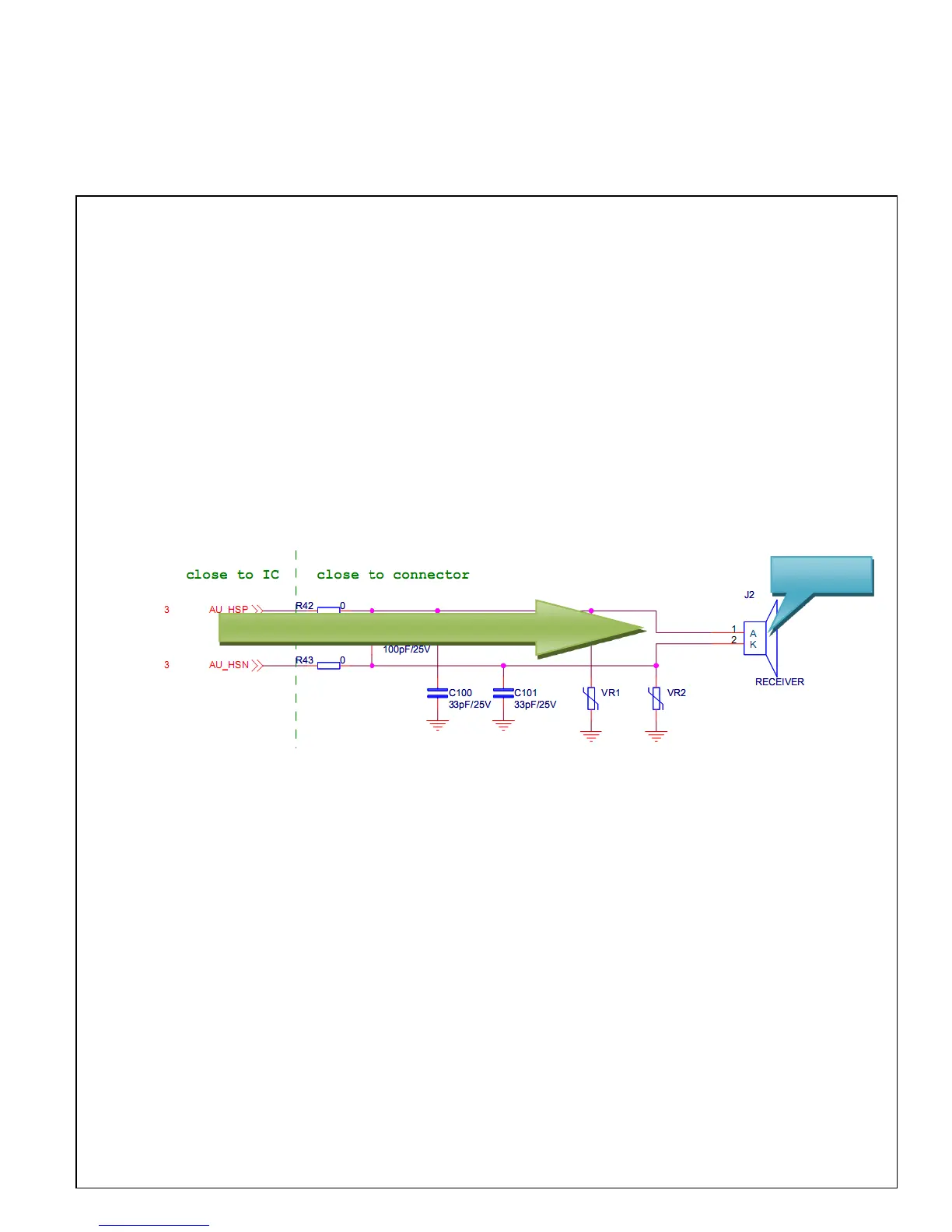
4.3.4 Receiver Circuit
Analog audio signals from CPU via filter circuit to drive receiver, then receiver produce
voice, so we can hear the voice which from the other phone.
If there is something wrong with the speech, please check the problem cause by assemble
or soldering process, then check receiver itself, it’s resistance is 32 ohms, otherwise to
check filter circuit and measure CPU’s output signal. Repair receiver function can refer to
the circuit.
Analog audio signal from CPU to receiver