K
Kelly WagnerNov 2, 2025
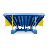
What to do if Blue Giant Lifting Systems deck will not raise?
- Cchristopher97Nov 2, 2025
If the deck of your Blue Giant Lifting Systems won't raise, several factors could be at play. First, check for any foreign material lodged between the side of the deck and the pit wall, and remove it. Another cause could be damaged or missing bumpers, which allows the truck to contact and hold the lip. Move the truck and replace the bumpers as needed. Also, make sure that equipment or goods aren't parked on the dock leveler deck. Low hydraulic oil fluid or a damaged hose causing an oil leak could also be the reason. In these cases, repair the hose and refill with approved hydraulic oil. For three-phase power supplies, incorrect motor rotation might be the issue, which requires a qualified technician to correct. Lastly, the relief valve may be bypassing. Try resetting the relief valve adjus...