EN
BL220 PERISTALTIC PUMPS
|
7
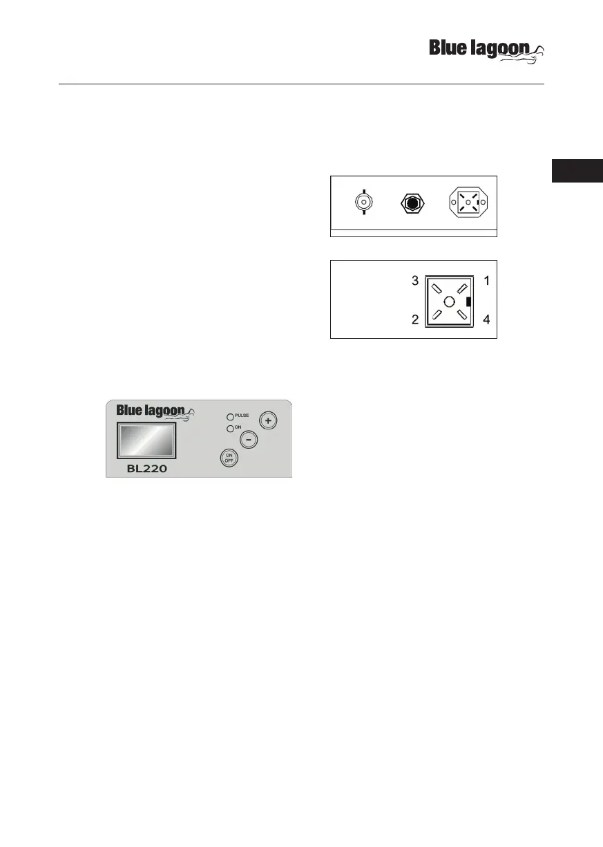
ELECTRICAL CONNECTIONS
Power supply: 230 V~, 50/60 Hz.
The mains circuit must be protected in accordance
with the relevant laws and regulations. Typically, the
protection is given by a 30 mA differential switch and
a breaker or 1 A fuse.
If a level control sensor is used, plug it to its connector
(see figure). Warning! If several pumps are connected
in parallel, always observe the polarity of the level
connection, not to endanger the proper functioning
of the system or damage the inputs!
Connect the measurement electrode to the BNC
connector.
CONTROL PANEL
Display during normal operations displays the measured pH or redox (mV); the following
messages may also appear:
- OFF the pump has been disabled by pressing the ON/OFF button
- LEU the level sensor consent is missing
- PAU the pump is “Paused” at start-up (also see “Configuration” section)
- ALL a dosage “Alarm” is active (also see “Configuration” section)
- UR measurement out of range, below the minimum value (Under-Range)
- OR measurement out of range, above the maximum value (Over-Range)
ON/OFF key enables/disables the system; press and hold for at least 3 seconds to enter the
CONFIGURATION mode
[-] key press and hold to display the electrode offset value (for 3 seconds) and then enter
the OFFSET CALIBRATION mode
[+] key press and hold to display the electrode gain value (for 3 seconds) and then enter the
GAIN CALIBRATION mode
PULSE LED red light; lights up during rotation of the peristaltic pump; if the automatic mode is
disabled (see “Configuration” section), the LED flashes quickly
ON LED green light; fixed ON indicates normal operations; flashes when an alrm occurs
Level Connector:
1 = N.C.
2 = N.C.
3 = level +
4 = level -