507787B02Issue 2336Page 12 of 22
Electric Shock Hazard. Can cause injury or
death. Unit must be properly grounded in
accordance with national and local codes.
Line voltage is present at all components when
unit is not in operation on units with single-
pole contactors. Disconnect all remote electric
power supplies before opening access panel.
Unit may have multiple power supplies.
WARNING
Electric Shock Hazard.
Can cause injury or death.
Foil-faced insulation has conductive
characteristics similar to metal. Be sure there
are no electrical connections within 1/2ʺ of the
insulation. If the foil-faced insulation comes in
contact with electrical voltage, the foil could
provide a path for current to pass through
to the outer metal cabinet. While the current
produced may not be enough to trip existing
electrical safety devices (e.g., fuses or circuit
breakers), the current can be enough to cause
an electrical shock hazard that could cause
personal injury or death.
WARNING
• Wiring must conform to the current National Electric
Code, ANSI/NFPA No. 70, or Canadian Electric Code
Part I, CSA Standard C22.1, and local building codes.
Refer to following wiring diagrams. See unit nameplate
for minimum circuit ampacity and maximum over-
current protection size.
• Electrical wiring, disconnect means and over-current
protection are to be supplied by the installer. Refer
to the air handler rating plate for maximum over-
current protection, minimum circuit ampacity, as well
as operating voltage. Select the proper supply circuit
conductors in accordance with tables 310-16 and 310-
17 in the National Electric Code, ANSI/NFPA No. 70 or
tables 1 through 4 in the Canadian Electric Code, Part
I, CSA Standard C22.1.
• The power supply must be sized and protected
according to the specications supplied on the product.
• This air handler is factory-congured for 240 volt,
single phase, 60 cycles. For 208-volt applications, see
“208 Volt Conversion” later in this section.
• Separate openings have been provided for 24V low
voltage and line voltage. Refer to the dimension
illustration of specic location.
• This unit is provided with holes for conduit. Use
provided caps to seal holes not used.
• Typical unit wiring (as well as wiring of optional eld-
installed electric heat) is given in Figure 16. Refer to
the instructions provided with the electric heat section
for proper installation.
USE COPPER CONDUCTORS ONLY
WARNING
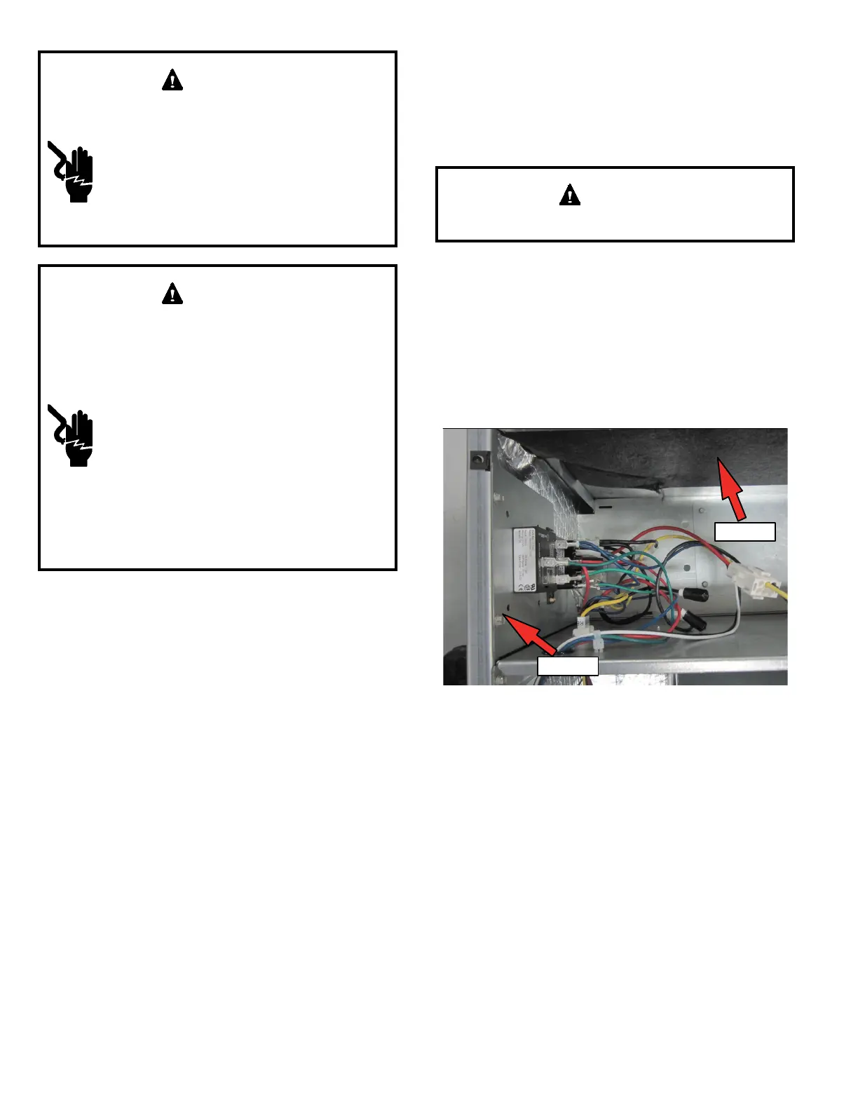
1. Disconnect all power supplies.
2. Remove the air handler access panel.
3. Route the eld supply wires to the air handler electrical
connection box.
4. Use UL-listed wire nuts to connect the eld supply
conductors to the unit black and yellow leads, and the
ground wire to ground terminal marked GND.
5. Replace the air handler access panel.
SIDE
TOP
Figure 11. Electrical Connections
(Upow Conguration)
Control Panel Relocation
To avoid the possibility of moisture damage to the control in
some left-hand discharge congurations, the control panel
can be relocated to the end panel as shown in Figure 13.
1. Remove the two screws that secure the control panel
to the cabinet. Slide panel out.
2. Slide the control panel into the notch on the electric
heat mounting panel (Figure 12). Using the screws
removed in Step 1, secure the control panel to the end
panel.