507787B02 Issue 2336 Page 13 of 22
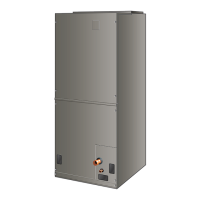
Figure 12. Notch for Control Panel Relocation
TOP
SIDE
Figure 13. Control Panel Relocated to End Panel
(Horizontal-Left Conguration)
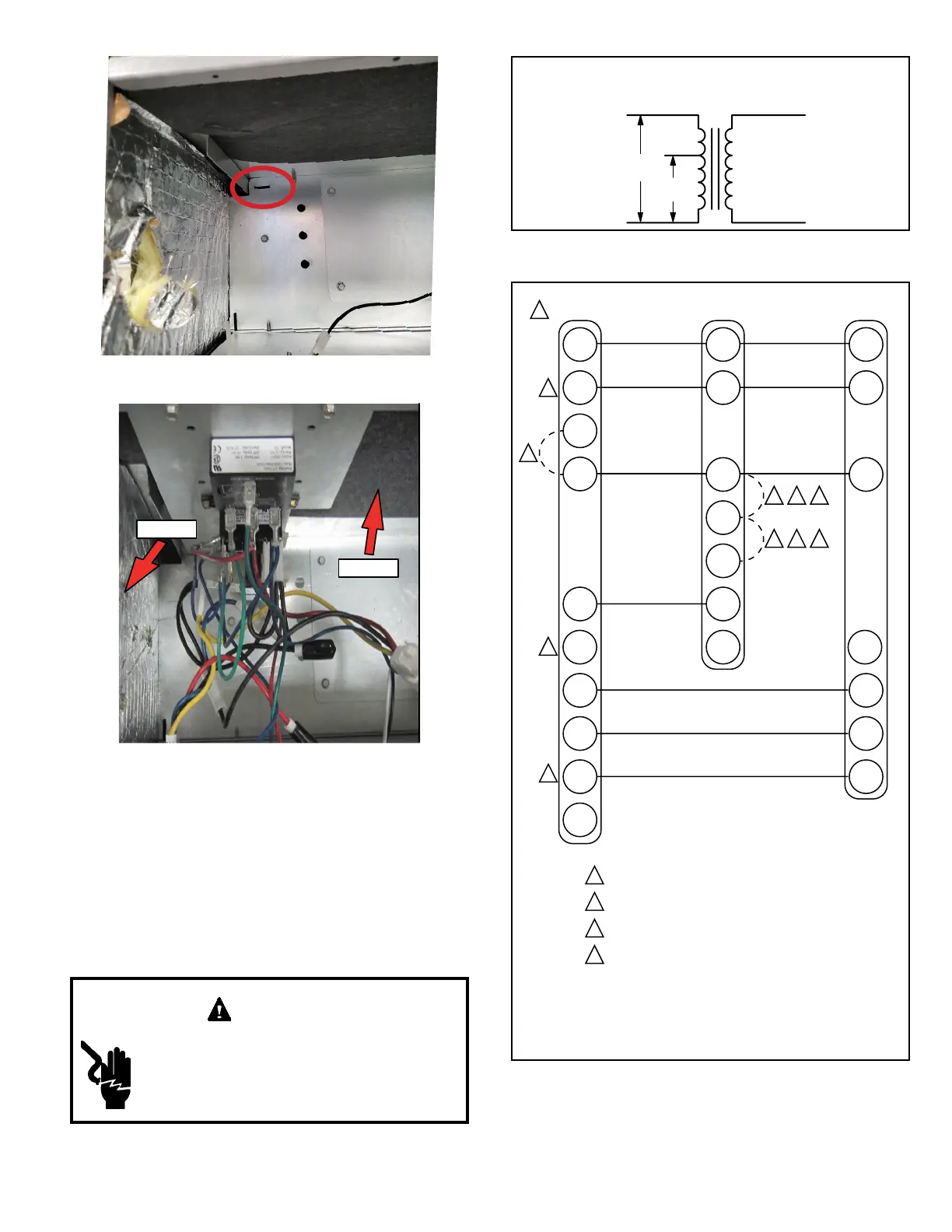
208 Volt Conversion
1. Disconnect all power supplies.
2. Remove the air handler access panel.
3. Using the wiring diagram located on the unit access
panel as a reference, move the 2 connected black
transformer leads from the 240 volt terminal on the
transformer to the 208 volt terminal on the transformer.
Electrically ground air handler. Connect
ground wire to ground terminal marked “GND”.
Failure to do so can result in death or electrical
shock.
WARNING
208 / 240 VOLT TRANSFORMER
PRIMARY SECONDARY
240 Volts
208 Volts
Figure 14. Converting Unit from 240VAC to 208VAC
Figure 15. Thermostat Designations -
Non-Communicating
1
Refer to thermostat installation instructions
2
If applicable
3
Refer to indoor unit installation instructions
4
“L” is used for any accessories (e.g. diagnostic /
warning / alarm), used to activate thermostat
warning light
W / W1 / W2 / W3 are auxiliary heat
(supplemental to heat pump).
“E” is emergency heat (disables heat pump).
NOTES:
W3
W2
R
R
R
C
C
C
W1
W/
W1
W1
Auxiliary Heat
(Heat Pump)
G
G
Indoor Blower Only
O
O
Heat Pump
Y2
Y2
Thermostat Indoor Unit Outdoor Unit
E
L L
B
Y1
Compressor / 1st Stage
Y1
4
1
2
31
2
31
2
1
1
Not Used
L
Auxiliary Heat
(Heat Pump)
Compressor / 2nd Stage