blueberry PLUS R2 Installation Manual 3.0 29
DANGER!
Make sure that the main switch of the Switchboard power supply that feeds the
blueberry charger product is set to the off position.
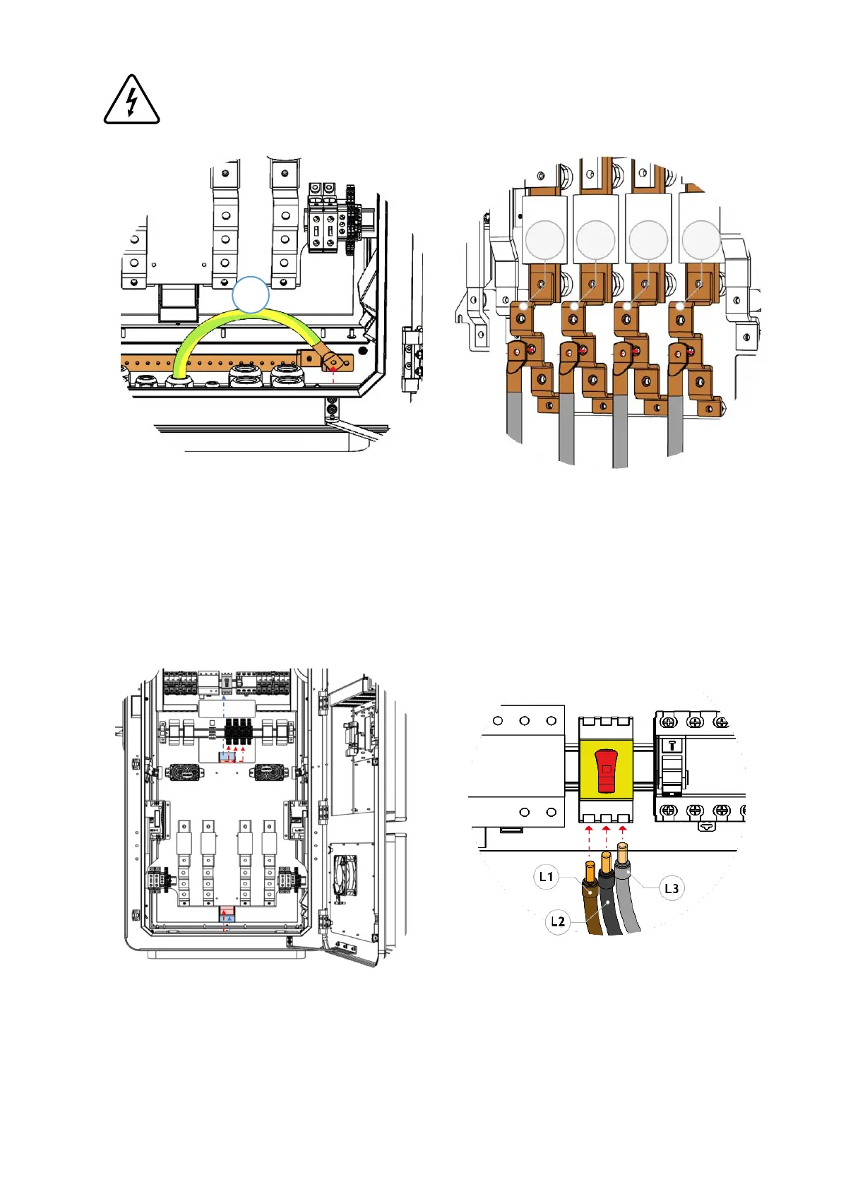
Step 5 - Connect the earth cable (cable nº1) to the
busbar placed in the bottom of blueberry PLUS –
User Unit, as shown in the image. For that, it is
necessary to crimp an M8 ring terminal on the cable
and then to tight it with an M8 x 20 screw on the
busbar, with a tightening torque of 28 N.m.
Step 6 - Connect the DC power conductors to the
busbars placed in the bottom of blueberry PLUS -
User Unit, as shown in the image.
For that, it is necessary to crimp an M8 ring terminal
on the cables and then to tight it with a M8 x 20
screw with its matching washer ant nut, applying a
tightening torque of 28 N.m.
Step 7 – Guide cables nº 5, nº6, nº12 and nº17 (if
applicable) through the conduit marked in red and
cable nº1 through the conduit marked in blue, both
placed behind the plate. Refer to Chapter 5.4 for
details on the cabling numbers.
Step 8 - Connect the AC power conductors to the
switch disconnector (S1). For that, it is necessary to
crimp an insulated single end terminal on each
cable. Connect the conductors with a tightening
torque between 1.8 N.m and 2 N.m.