DANGER!
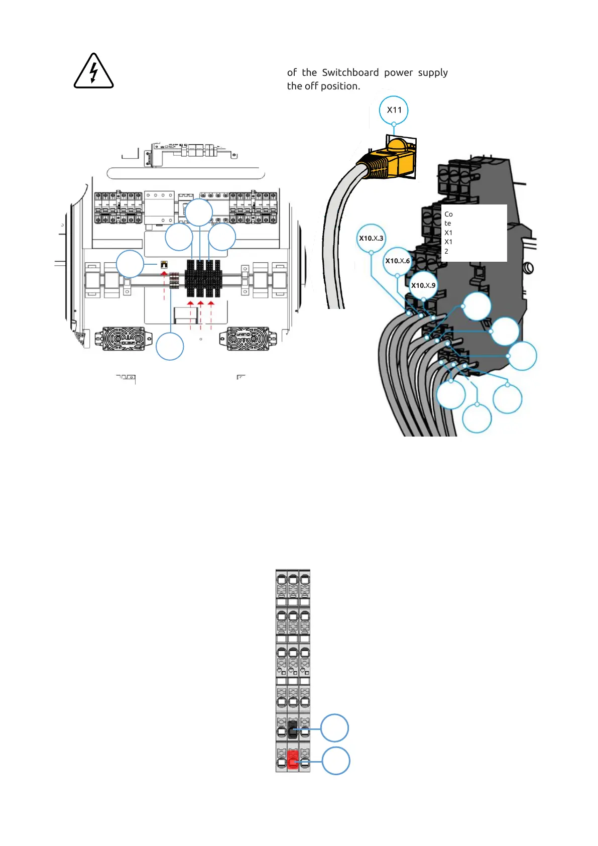
Make sure that the main switch of the Switchboard power supply that feeds the
blueberry charger product is set to the off position.
Step 9 - Connect the signal conductors and the ethernet cable to the terminal blocks X10.1, X10.2 (if
applicable – 2
nd
Power Unit), X10.3 (if applicable – 3
rd
Power Unit) and X11, as shown in the image (Refer to
Chapter 5.4 for interconnections details). For that, it is necessary to crimp single end terminals on each line of
the shielded cable.
Before connecting X10.2 / X10.3, it will be necessary to disconnect red and black lines in both ends (X43 to
X10.2 / X10.3), marked in the figure below. Please note that this is only to be done when it is necessary to
connect X10.2 (two Power Units) or X10.2 and X10.3 (three Power Units).
After that, place the bottom plate that was removed in step 1 with the same fasteners.