15
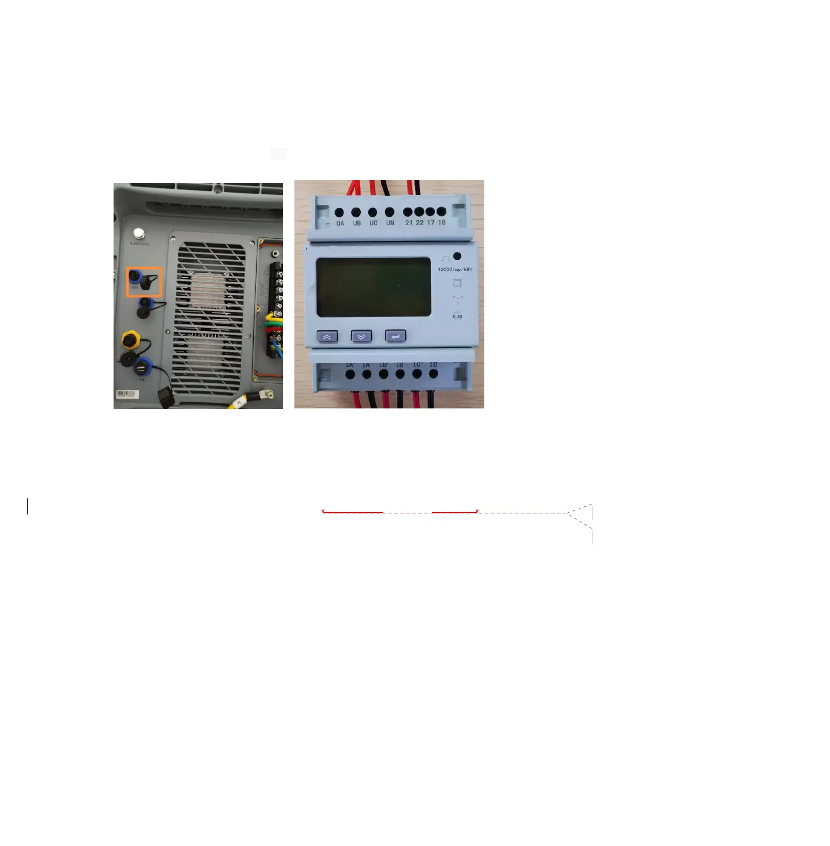
4.11.3 Please connect the Meter communication cables to the COM Port of the EP600;
The Meter is only applicable to the case where the PV grid-tied inverters have been
installed.
1) Connect the cables of UA UB UC UN to the L1/L2/L3/N of the PV inverter,
2) Connect the cables of the CT to the Meter and tied to the wires of L1/L2/L3 of the PV inverter.
3) Please connect the 485-A red wire to pin 21,485-B black wire to pin 22.
4.11.4 Transfer Switch circuit connection
4.11.4.1 About Transfer Switch
Transfer switch is necessary for building a partial residential backup system.
NOTES:
Before installing the EP600, please read following notes carefully:
1) Switch to I means the electrical power is from the EP600. Owners can switch to I until
faults occur to EP600.
2) When faults occur to EP600, we need to switch to II to use the public grid.
3) If the public power grid is always outage, please switch to I to use EP600 UPS mode, if
not, switch to II.
 Loading...