22 | P a g e
system.
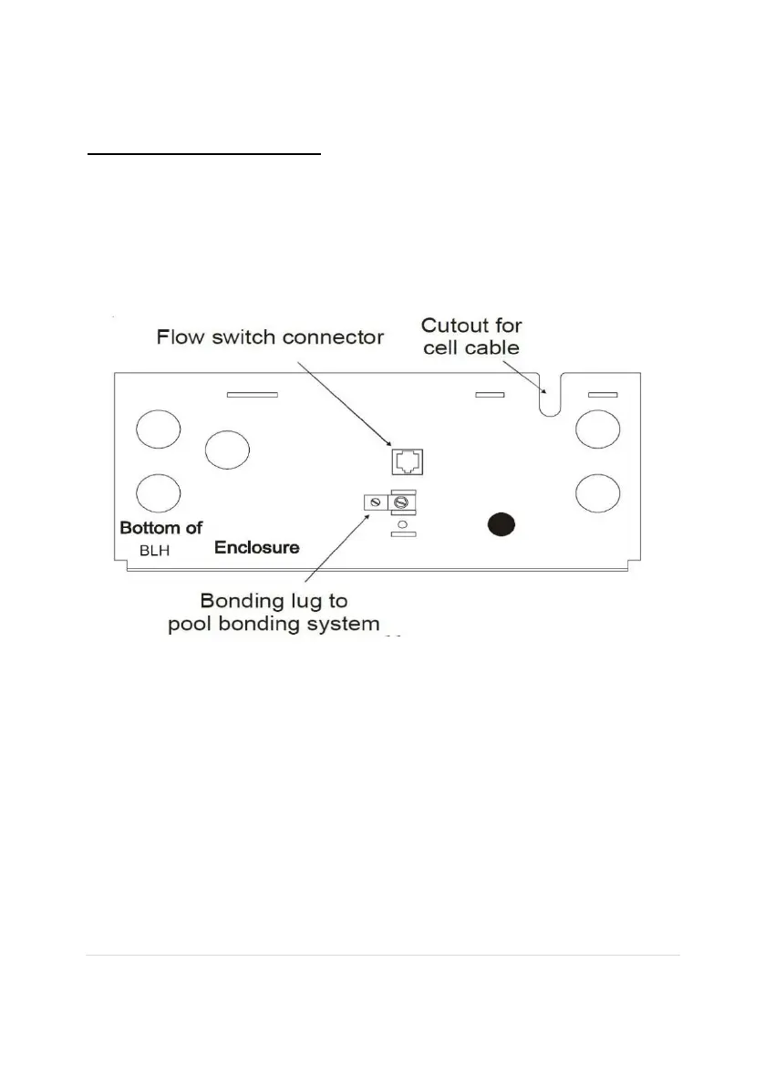
Electrolytic Cell and Flow Switch:
The electrolytic cell and flow switch cables are complete with connectors that plug into the
BLH for easy attachment and removal. The door of the BLH must be open to access the cell
cable connector. The flow switch plugs into a connector (like a telephone jack) located on
the outer bottom of the enclosure. Refer to the diagram below for the location of these
connections.
Input power for use with Goldline, Pentair and Polaris controllers:
Wire the BLH® DIRECTLY TO 120/240vac POWER (not through timer or relay).
Optional Goldline, Pentair and Polaris controllers:
The Goldline, Pentair and Polaris controls use a 4-wire connection to communicate to the
BLH and can be wire up to 500’ apart. Any outdoor rated 4 conductor cable can be used.
Refer to each manufacturer’s instructions and the wiring diagrams below for proper wiring
connection to the BLH.
NOTE: There must be only 1 “primary” unit. All additional BLH units must be configured as
“secondary”.
Goldline: Attach wires to proper screw terminals as shown below.