Note: the rear brake stopper has a flat surface on the retaining wall, differentiating it with the DO stopper (described in
point 6. of section “Cable routing for mechanical gear shifting”).
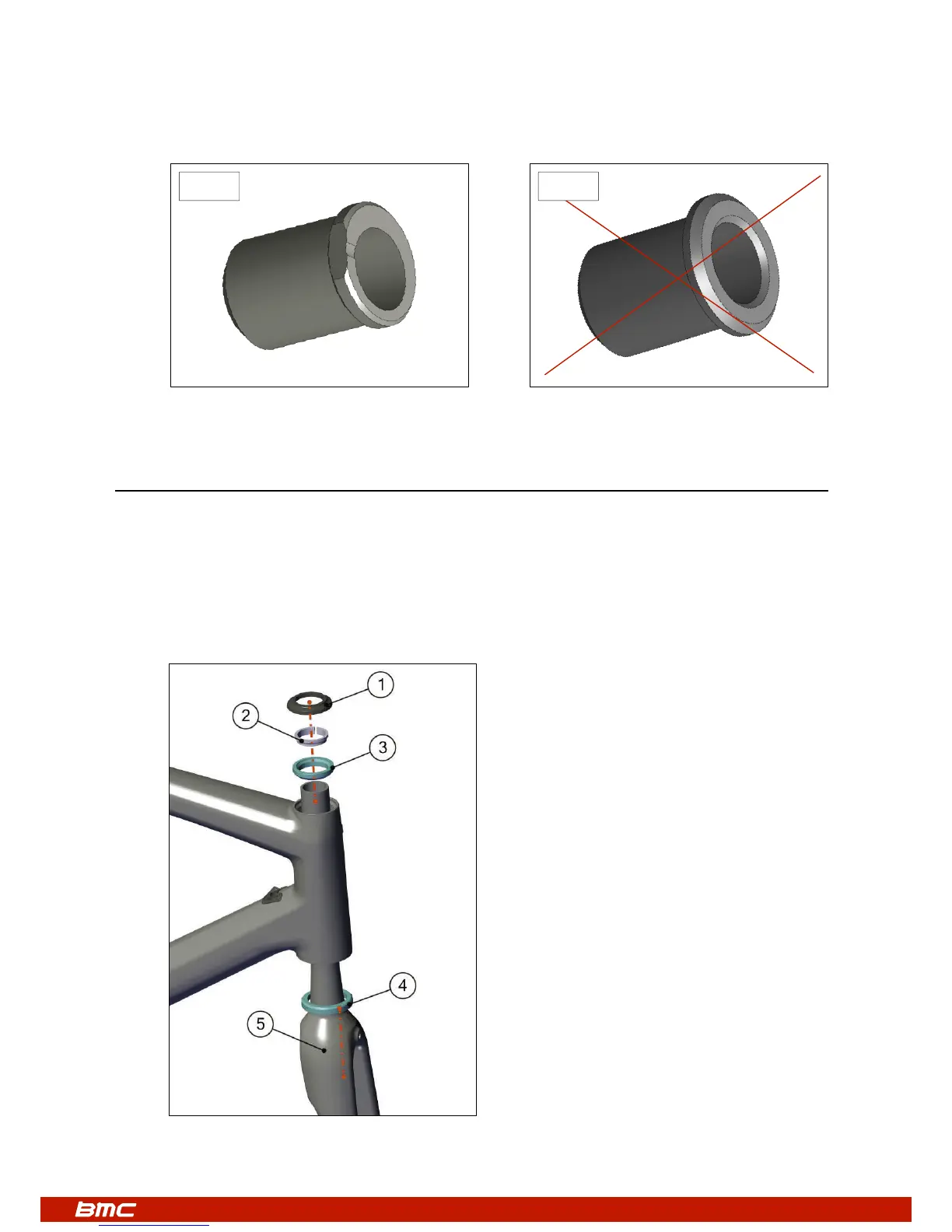
Headset and Fork Installation
1. Apply grease on the bearings (N°3 and 4) and on the bearing seats of the frame. Place the bearings in the frame.
2. Apply grease on the shaft and on the crown of the fork (N°5), and then slide it through the bearings and the head tube.
3. Slide the compression ring (N°2) over the fork shaft.
4. Slide the top cap (N°1) over the compression ring and then setup your stem.
Note: 2 different heights of top caps are delivered with the frame (low=8mm, high=15mm).
Feel free to use the one which matches your position the best.
Note: the fork crown is designed so that the lower bearing can seat directly on it. There is no need to add a metal ring.
YES NO