9. Install the Di2 plug at the drop out.
10. Install the Di2 grommets. Please refer to Shimano instructions.
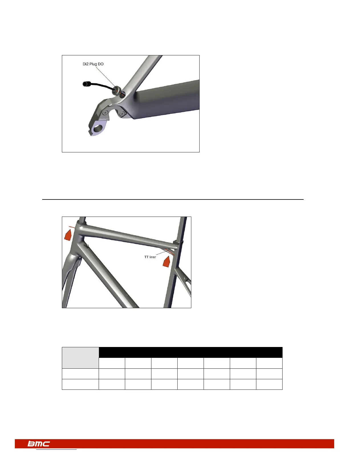
Rear brake cable
1. Make sure that the frame is ready for the rear brake cable routing by checking the liner’s presence through the top tube.
2. Please refer to the following chart in order to pre-define the length of the rear brake cable housing.
This length (in mm) is measured from a point on the handlebar 60mm away from the center of the stem to the cable entrance
at the head tube:
* the spacers height includes the conical top cap below the spacers (low=8mm or h
igh=15mm)
** the reference stem has an angle of -6°
Note: this table should be used as a guide only.
Spacers Stem length** (mm)
height* 80 90 100 110 120 130 140
<30mm 180 190 195 200 210 215 220
>30mm 185 195 200 205 215 220 225