10
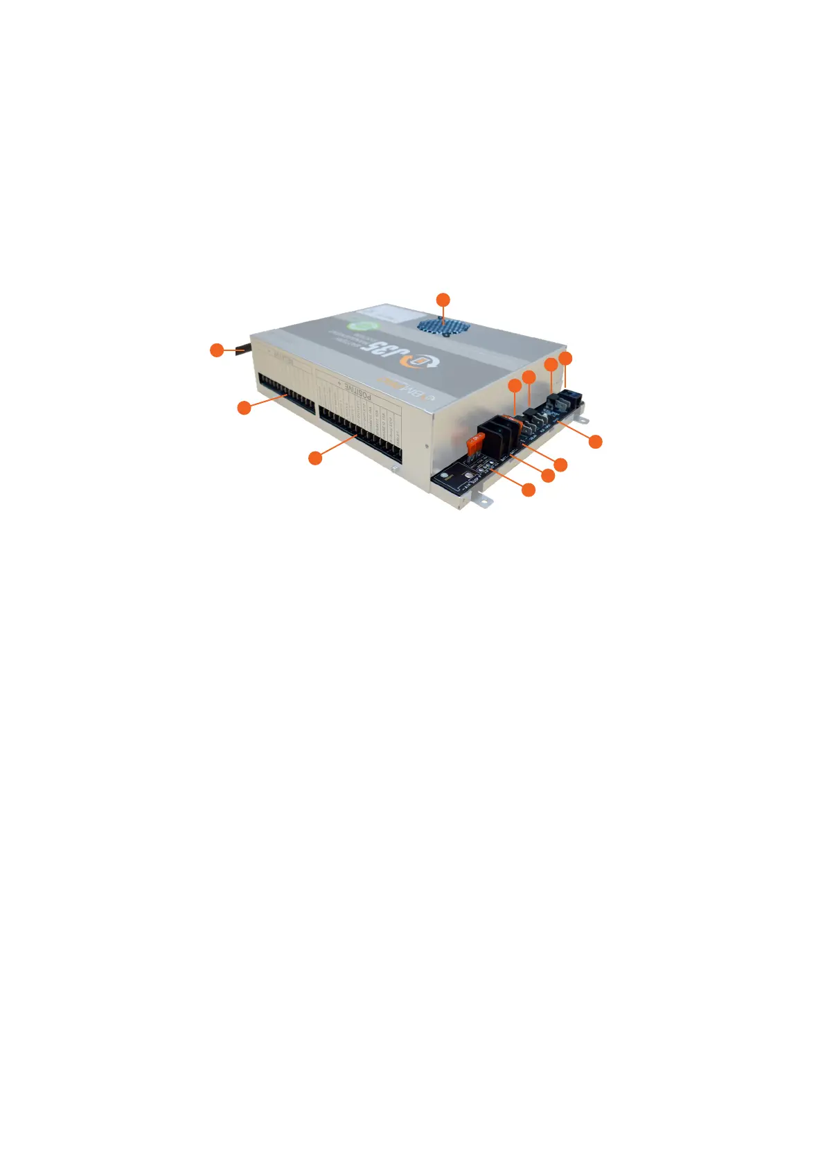
DESCRIPTION OF PARTS
1. MAINS CABLE
The J35 is pre-cabled with a permanent mains power supply cord. The AC mains
input is protected by a quick acting, high breaking capacity type fuse (rated
250V, 10A).
2. LOAD TERMINAL BLOCK – COMMON NEGATIVE CONNECTION
Negative wire connection point for the caravan’s 12V loads.
3. LOAD TERMINAL BLOCK – POSITIVE CONNECTION
Positive wire connection point for the caravan’s 12V loads.
To control loads from the JHub App, each load must be connected to the correct
terminal. Terminals are labelled according to their designated load output.
Each output is protected by an internal, electronic, auto-recoverable fuse. This
eliminates the need for the user to replace a blown fuse. If an electronic fuse is
activated, the LED Status Indicator on the J35 will flash a solid red. The J35 will
power off the faulty load and resume normal operation once the fault is fixed.
For details on the outputs, refer to J35 Designated Terminal/Load Outputs.
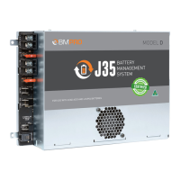
J35
1
2
3
4
9
10
11
12
8
5
6
7