4
2. Mounng the remote
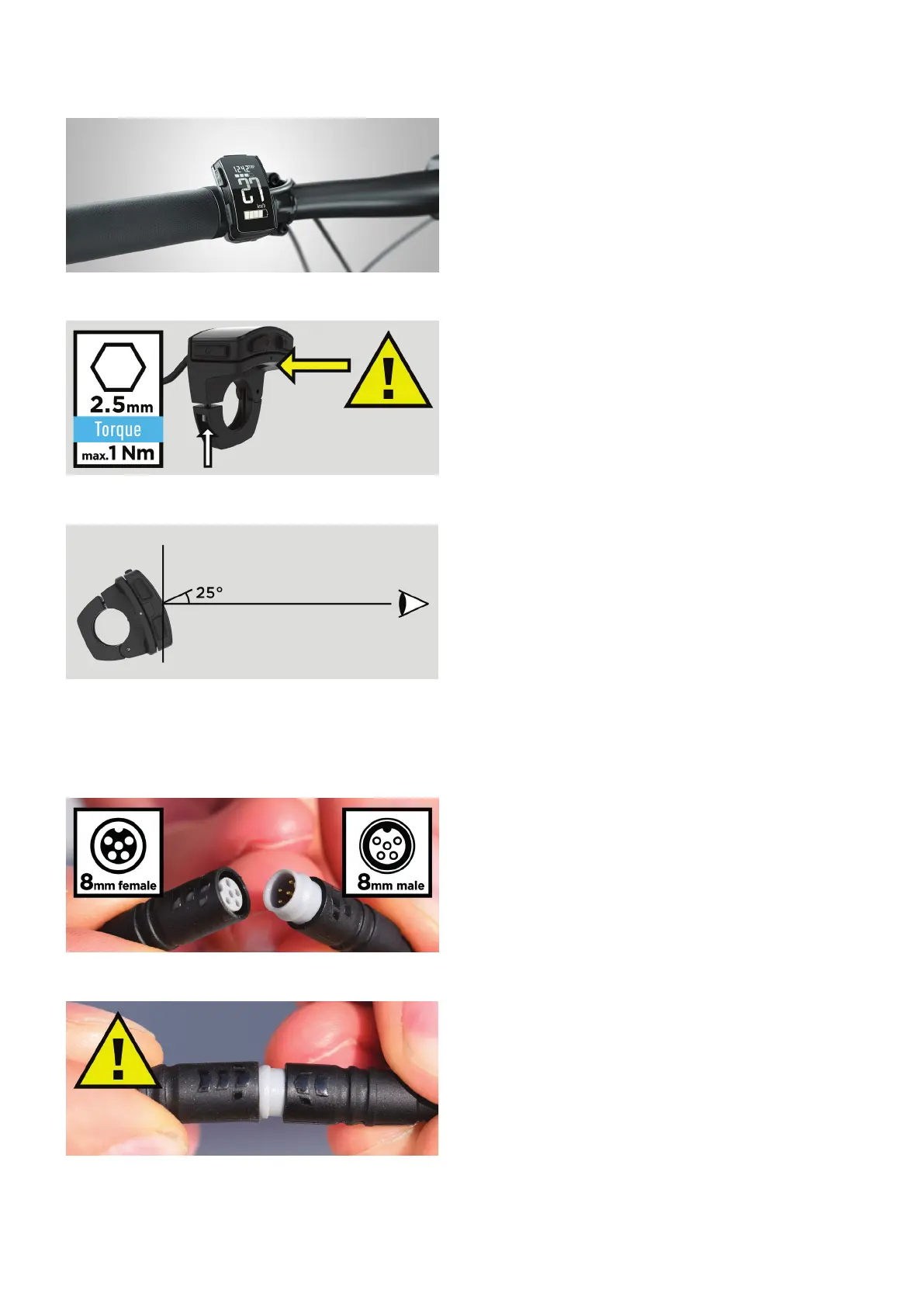
The BLOKS. remote is mounted on the le side of your pedelec’s
handlebars [Fig. 1]. The enre surface of the LCD display acts as a
rocker switch for the sengs "+" and "-". The remote also has three
buons; two on the side and one at the front. With the switch and
the buons, you can change the sengs on your pedelec, such as the
motor’s support level, at any me without taking your hands o the
handlebars.
When mounng the remote, keep the following in mind [Fig. 2]:
Torque: The remote is fastened with a 2.5mm hex head screw. Please
do not apply more than 1 Nm (newton meter) of torque to the screw.
Cauon: Make sure that nothing on the handlebars like the grip or
the brake lever is pressing against the side or underside of the remote
(yellow arrow). This could interfere with the funcon of the rocker
switch.
The display is designed in such a manner that the opmum viewing
angle is 25 degrees under the perpendicular [Fig. 3]. Loosen the fas-
tening screw and lt the display on the handlebars unl you nd the
best angle for your riding posion. Then refasten the screw, not using
more than 1 Nm of torque.
3. Connecng the remote's plug
If you need to open the two ends of the plug located on the cable
that goes from the BLOKS. remote to the pedelec’s frame, please
observe the following instrucons when reconnecng the plug.
The male plug on the cable comes from the remote [Fig. 4, right], the
female plug is on the other end of the cable [Fig. 4, le].
Cauon: The plugs must be aligned correctly when being connected.
Both plugs are provided with markings – align the markings on the
plugs [Fig. 5].
[Fig. 1] Remote mounted on the handlebars
[Fig. 2] Proper torque, avoid pressure against the housing
[Fig. 3] Best viewing angle
[Fig. 4] Female and male plugs
[Fig. 5] Align plug markings


 To Next Page