J SERIES M ICROV A CJ SERIES M ICROV A C VA CUUM PUM P V A CUUM PUM P
PAGE 2 -2
A high vacuum valve (full opening type preferred) is recommended to facilitate start-up and for checking pump
blank off pressure.
CAUTION:CAUTION: M ake sure M ake sure the system to be evacuated and connecting lines are clean and free of w eld splatter, dirt or the system to be evacuated and connecting lines are clean and free of w eld splatter, dirt or
grit. Foreign matter entering the pump can cause failure and possibly damage the internal parts. To grit. Foreign matter entering the pump can cause failure and possibly damage the internal parts. To
prevent this it is recommended that a 16 mesh w ire screen be prevent this it is recommended that a 16 mesh w ire screen be installed at the inlet connection. After 20 installed at the inlet connection. After 20
hours of operation the screen must be removed.hours of operation the screen must be removed.
2.2.1 Types of Piping Joints
A. Standard w rought piping with w elded joints makes the best vacuum piping system.
B. Copper piping with sw eated fittings and joints can also be made vacuum tight and has the advantage of
providing a neat, clean vacuum installation.
C. Standard threaded piping, however, is satisfactory and more readily installed. The piping should be
carefully hammered to loosen any scales or chips. Blow out any resultant debris with compressed air
prior to installation. All male threaded joints should be carefully doped, screwed tight and NEVER
“ backed-off” to make parts align - this is apt to cause a leak. Paint the joints w hile the system is under
vacuum until the paint is no longer draw n in, G.E. 1201-B, Glyptal or equivalent is recommended for
painting all connections.
2.2.2 Location of Gage Port
A vacuum gage connection is located at the upper left hand side of intake side of the pump. (See Figure 7). The
1/4" pipe plug found at this location should be replaced w ith a small vacuum ball valve to w hich the gage can be
connected. When a Stokes M cLeod Gage is used a synthetic, thick wall, smooth bore tubing, such as
Tygon,makes a very satisfactory flexible connection. To prevent oil from entering the gage, locate the gage
approximately 2 ft. (610 mm) above the port.
2.32.3 Exhaust PipingExhaust Piping
CAUTION:CAUTION: Never place a valve in the exhaust line. If a valve must be installed in the line, a relief valve must alsNever place a valve in the exhaust line. If a valve must be installed in the line, a relief valve must also be o be
inserted in the line betw een the reservoir and the valve. The relief valve should be equal in size to the inserted in the line betw een the reservoir and the valve. The relief valve should be equal in size to the
line, and set to open at 2 psig.line, and set to open at 2 psig.
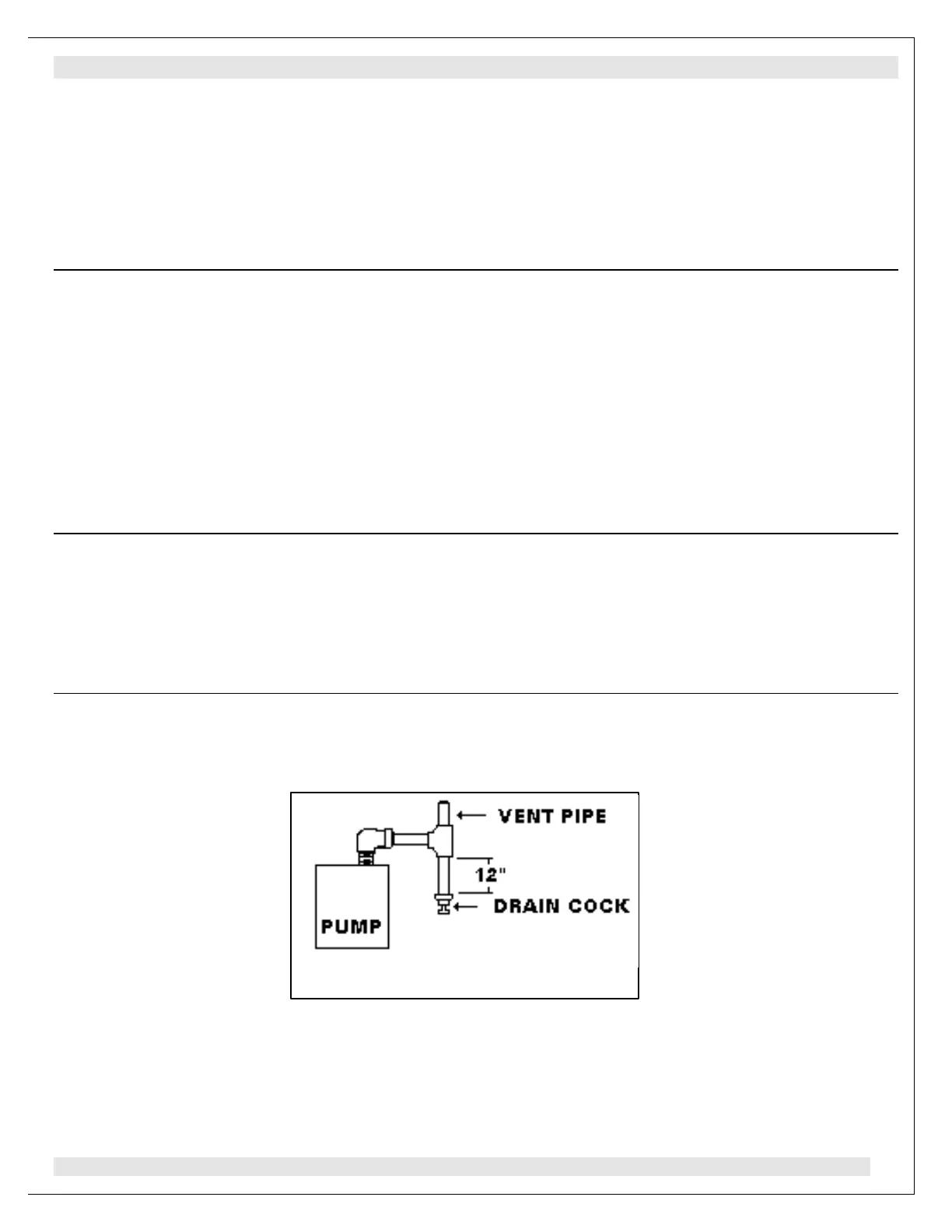
2.3.1 It is recommended that the exhaust be piped horizontally a short distance and tied into a vertical
exhaust pipe. The vertical exhaust pipe must be at least 12" (305 mm) long w ith the bottom end
terminated with a plug or a drain cock to allow removal of moisture and contaminated oil before
it can accumulate sufficiently to drain back into the pump oil reservoir. See Figure 4.
EX HAUST PIPING FIGURE 4EX HAUST PIPING FIGURE 4