Produkt.pm6.5 - USA
Page 2.7
Product description
BOGE Operating instructions for S 40-2...S 341 / SF 40-2...SF 220 series screw compressors
Function principle
of the air end
Air circuit
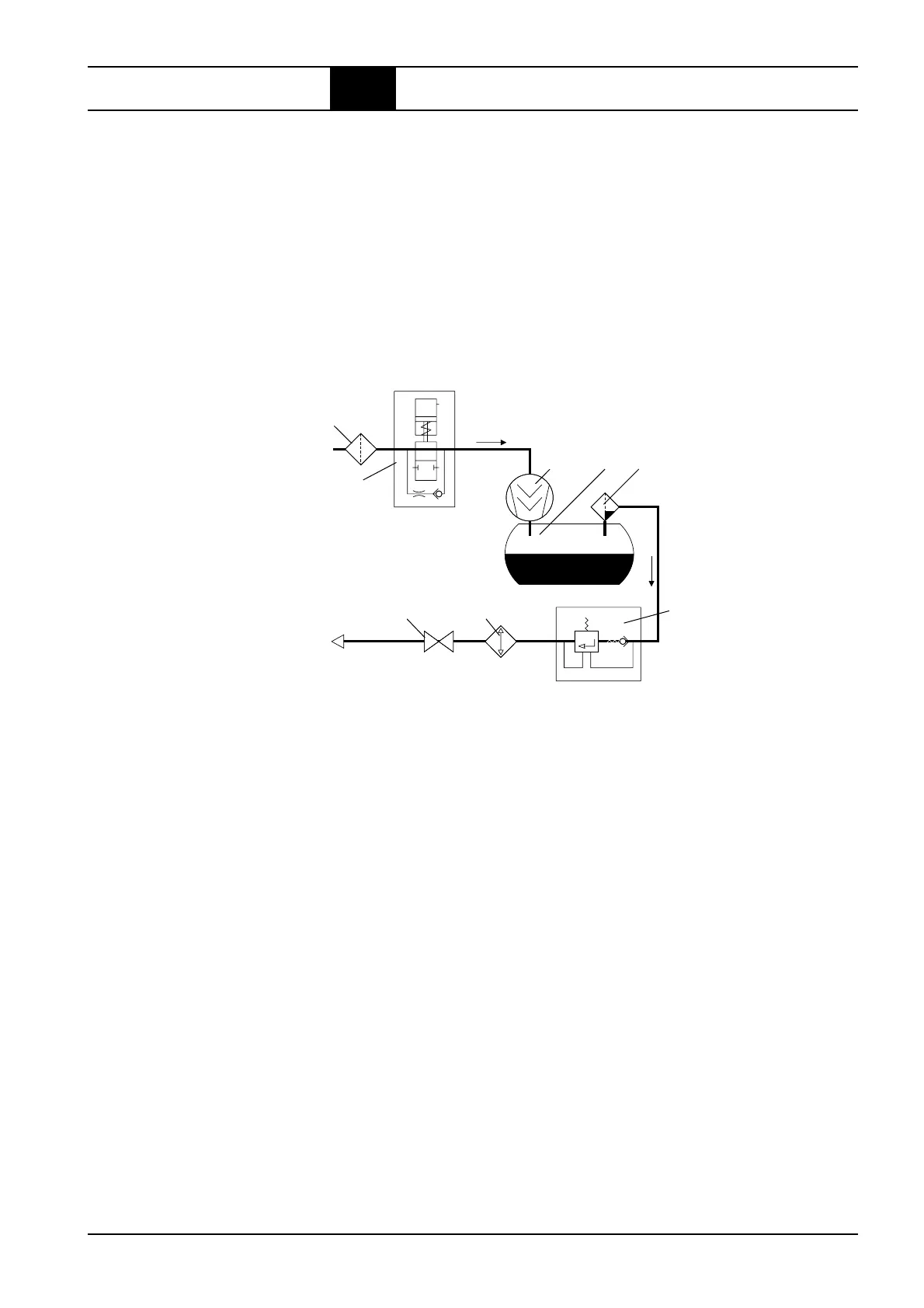
Fig. 2.1:
Components of
the air circuit
78
6
543
2
1
The air end operates according to the displacement principle. In the housing,
the main and secondary screws are driven by means of an electric motor
and V-belt.
Both screws have screw-shaped profiles, intermeshing without contact.
Together with the housing wall, these screws form chambers which gradually
reduce in size, seen in air flow direction.
Rotation of the rotors causes the air taken in to be compressed to the final
pressure in the chambers.
During compression oil is continuously injected into the air end. This having
a cooling, sealing and lubricating function.
1 = Intake filter
The intake filter cleans the air suctioned by the air end.
2 = Intake regulator
The intake regulator opens (load operation) or closes (idling operation or
standstill) the intake line depending on the operating condition of the com-
pressor.
3 = Air end
The air end compresses the intake air.
4 = Compressed air/oil receiver
The compressed air separates from the oil under the force of gravity in the
compressed air/oil receiver.
5 = Oil separator
The oil separator separates the residual oil contained in the compressed air.
6 = Minimum pressure check valve
The minimum pressure check valve does not open until the system pressure
has increased to 3.5 bar (51 psig). This causes a rapid build-up of the system
pressure and ensures lubrication in the starting phase. Once the compressor
has been switched off, the check valve prevents the compressed air from
flowing back out of the mains line.
7 = Compressed air after-cooler (air and water cooled)
The compressed air is cooled in the compressed air after-cooler, causing the
water contained in the air to condensate.
8 = Stop valve
The screw compressor may be isolated from the mains by means of the stop
valve.
2.2 Function description
 Loading...