ASSEMBLYINSTRUCTIONS
ASSEMBLING THE UNIT
Before operating, position the unit's handlebars.
NOTE: You may also need to reposition the wheel
height before using the cultivator. Refer to the
Adjusting Tine Depth section.
Begin by carefully unpacking the contents and making sure
that nothing is damaged.
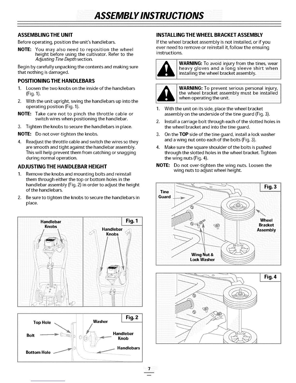
POSITIONING THE HAN DLEBARS
1. Loosen the two knobs on the inside of the handlebars
(Fig. 1).
2. With the unit upright, swing the handlebars up into the
operating position (Fig. 1).
NOTE." Take care not to pinch the throttle cable or
switch wires when positioning the handlebar.
3. Tighten the knobs to secure the handlebars in place.
NOTE: Do not over-tighten the knobs.
4. ReadJust the throttle cable and switch the wires so they
are smooth and tight against the handlebar assembly.
This will help prevent them from catching or snagging
during normal operation.
ADJUSTING THE HANDLEBAR HEIGHT
1. Remove the knobs and mounting bolts and reinstall
them through either the top or bottom holes in the
handlebar assembly (Fig. 2) in order to adjust the height
of the handlebars.
2. Be sure to tighten the knobs to secure the handlebars in
place.
INSTALLING THE WHEEL BRACKET ASSEMBLY
If the wheel bracket assembly is not installed, or if you
ever need to remove or reinstall it, follow the ensuing
instructions.
WARNING: To pievent Serious personal injury,
the wheel bracket assembly must be installed
when operating the unit.
1. With the unit on its side, place the wheel bracket
assembly on the underside of the tine guard (Fig. 3).
2. Install a carriage bolt through each of the slotted holes in
the wheel bracket and into the tine guard.
3. On the TOP side of the tine guard, install a lock washer
and a wing nut onto each of the bolts (Fig. 3).
4. Make sure the square shoulder of the bolts is pushed
through the slotted holes in the wheel bracket. Tighten
the wing nuts (Fig. 4).
NOTE." Do not over-tighten the wing nuts. Loosen the
wing nuts to adjust wheel height.
Fig. 3
Wheel
Bracket
Assembly
Lock Washer
I F'g'
Washer I Fig. 2
Bottom Hole _''
Handlebar
Knob
 Loading...