19 / 52
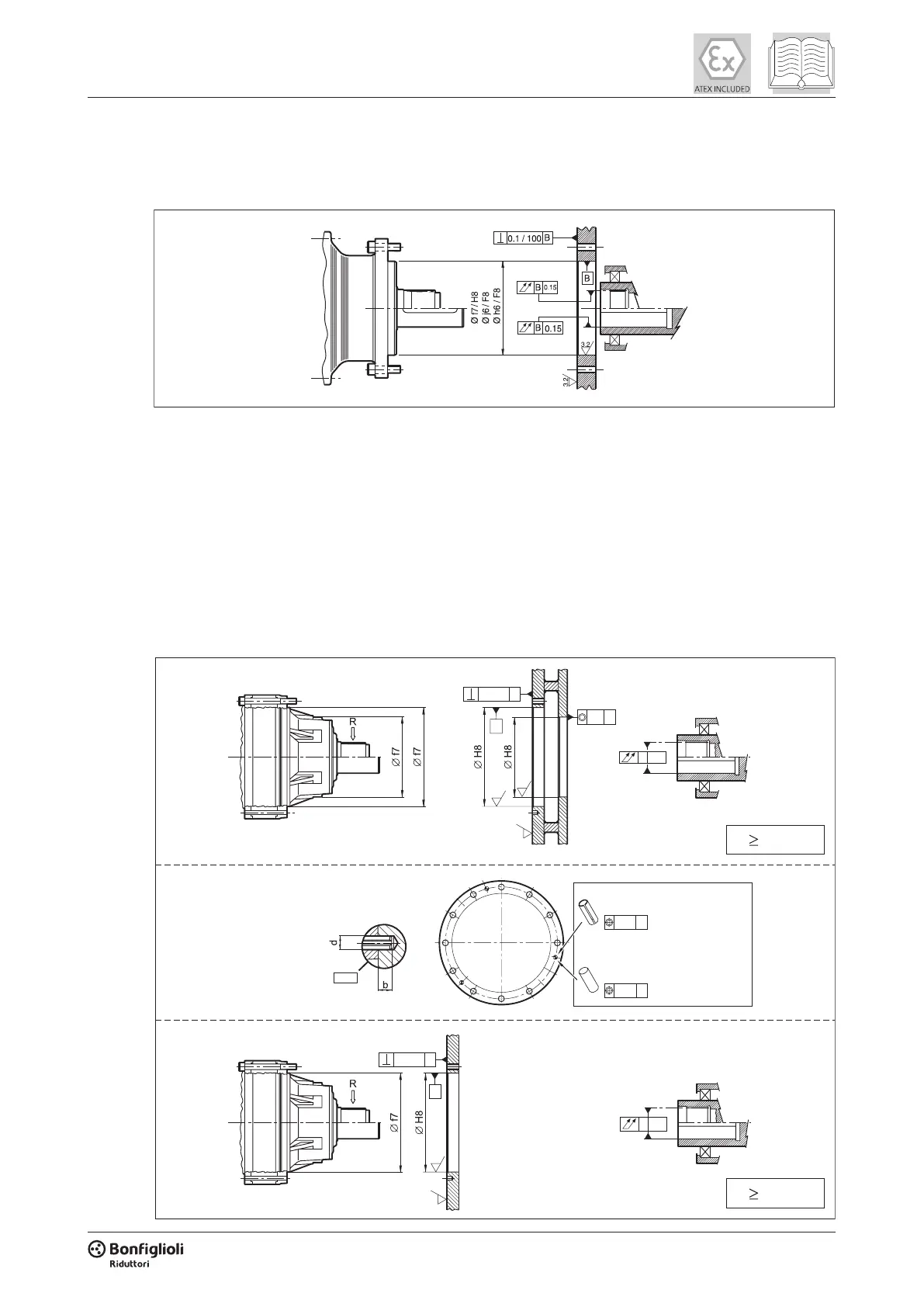
For machining the spigot on the driven machine, refer to the diagrams below:
300...307 gear units - male output shaft motor execution
309...321 , 310M...318M gear units - male output shaft motor execution
These gear units are tted with two spigots. When machining the coupling anges, one spigot
may be sufcient if the output shaft is not subject to overhung loads or loads are less than 60% of
the permissible load.
For heavier loads, the mounting must use both spigots on the gear unit.
If the gear unit is instead required to transmit high torque or is subject to heavy shock loads and
inversions in the direction of rotation, the counterange must be drilled to accept the spigots.
At the time of installation, move the spigots mounted on the gear unit forward into the counter-
ange by an amount equal to their diameter. See diagram below:
300...307
0.07
B
B
0.15
B
0.1 / 100
B
3.2
3.2
3.2
b = d
0.1 / 100
B
B
0.15
B
3.2
3.2
0.20
B
0.05
B
309...315 , 310M...315M
316...321 , 316M...318M
R 60% Rn
R 60% Rn
316 ... 321 , 316M ... 318M
UNI 6364 Ø25 x 2b
309 , 310 , 310M
UNI 6873 Ø12 x 2b ; Ø16 x 2b
Dowel pin borne
by the customer
 Loading...


