26 AGL-STOV0-01SV0-05
06/12
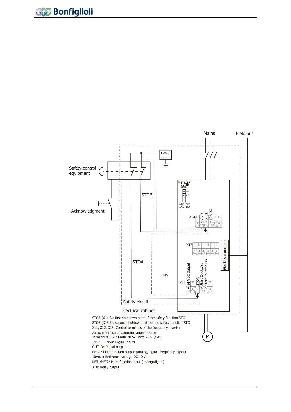
10.1 STO according to Stop Category 0
10.1.1 STO Direct Stop
The Application example shows the minimum circuitry for Agile Frequency inverter for
realization of the safety function STO – “Safe Torque Off” with an emergency stop
device in a common electrical cabinet according to EN ISO 13849-1 PL d and Catego-
ry 3 or IEC 61508 SIL 2.
When operating the emergency stop device with two stop channels both release
paths paths STOA and STOB of the Agile frequency inverter are interrupted and the
integrated safety function is triggered by interrupting the inverter release. A (non-
safe) feedback to a process control can be done via a connected field bus. When STO
is requested, the process controller can no further influence the inverter release in-
side the frequency inverter.
Note: Terminal X11.1 can be used for DC 24 V supply of the safety control unit.
Please comply with chapter 7.3.1.

 Loading...


