AGL-STOV0-01SV0-05
06/12
35
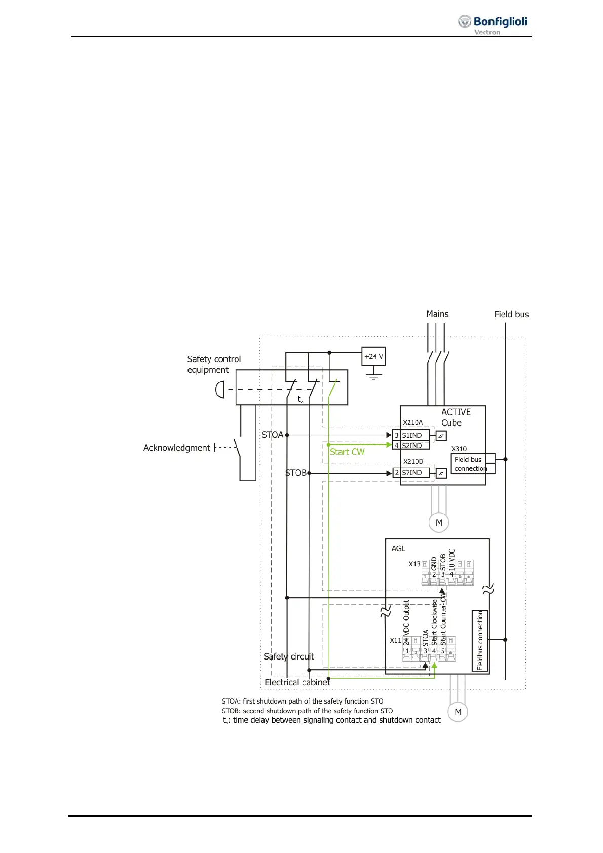
10.4 Group Stop, SS 1
The application circuit shows a drive control system with PLC and safety module ac-
cording to EN ISO 13849-1 PL d and Category 3 or IEC 61508 SIL 2. A PLC performs
the process control of the frequency inverter and can start the drive profiles via
commands which are communicated through the field bus.
If the protective device is actuated, e.g. emergency stop switch, the enable paths of
the safety module are interrupted. At first, the travel signal “Clockwise” is reset.
Then, the motors are decelerated in a controlled way. After a delay t
v
, the controller
enable signal of the frequency inverters is interrupted via the disconnection of the
control voltages from STOA and STOB and the integrated safe pulse block is acti-
vated.
Via the field bus, the (non-safe) feedback is transmitted to the PLC indicating that the
drives have stopped. Except for the terminals shown in the diagram, no further ter-
minals are required for connection.
Note, that with high current demand a fuse leading to the safety contacts might be
necessary according to the instructions of the safety device manufacturers.
The external DC 24 V supply must be dimensioned accordingly, see chapter 7.3.1.
In group stop
setup
s pulsed signals could lead to more frequent false trippings.

 Loading...


