23 / 64
IOM Manual VF-W_ATEXgb - Translation of original instructions in Italian - Rev 03_0 - 30/09/16
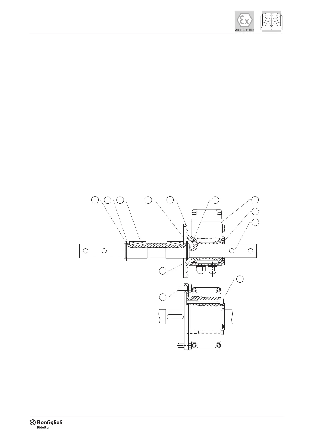
3) Preheat the bushing (2) and pinion (1) to 80-100°C.
4) Quickly t to the motor shaft, in succession: the bushing (2), key (3) and pinion (1). When tting the
bushing (2), ensure that the side with the chamfer for the seal ring is facing you. To facilitate mounting,
lightly press on the parts being tted (e.g. with a tubular drift). Make sure that the reaction force in
this case is supported by the opposite end of the shaft, and not by the fan cover. At the end of this
procedure the pinion (1) should be snug against the bushing (2).
5) Secure the assembly axially with the spacer (4) and washer (5) and tighten the bolt (6) to the specied
torque. Alternatively, for congurations which have this option, t the stop bushing (B1) and hold it
snug against the pinion (1) while tightening the two grub screws (7). See the gure at the right.
6) Lubricate the seal ring lips with a lm of grease.
7) For type VFR 49 gearboxes, which are lubricated for life and hence do not have a service plug, ll with
the quantity of lubricant specied in the lubrication chapter of the VFR catalogue.
8) Grip the motor rmly and, holding it in alignment, mount it to the ange of the rst reduction stage. Take
the greatest care to avoid denting the pinion or gear wheel teeth.
9) With the motor and gearbox anges in contact, fully tighten down the xing bolts (8), proceeding
gradually and in a cross-wise pattern.
10) Lubricant must be changed periodically on VFR 130 to VFR 250 gearboxes. For these gearboxes the
lubricant charge is given in the “LUBRICATION” section of this manual. Check that the correct level
has been reached via the sight glass, with the gearbox in its specied mounting position. Top up as
necessary.
5.5 INSTRUCTIONS FOR THE ASSEMBLING OF THE LIMIT-SWITCH DEVICE (RVS) ONTO GEARBOX
5
5
4 2
4
6
1
10
9
3
8
7
1. Make sure that the limit-switch device (10), as well as the mounting kit for the specic gearbox, is
available in the required conguration.
2. Start assembling the components of the mounting kit rst. Insert the dowel pin (1) and keys (2) into their
sites. Then slide shaft (3) into the hollow shaft of the gearbox. The position of the dowel pin (1) will dene
the side the limit-switch (10) ts onto.
 Loading...