21 / 64
IOM Manual VF-W_ATEXgb - Translation of original instructions in Italian - Rev 03_0 - 30/09/16
5.2 ANCHORING THE TORQUE ARM
For shaft-mounted solutions, on request, the gearbox can be equipped with a torque arm.
This device comes complete with an anti-vibration bush (included in the supply except with VF 30, VF 44
and VF 49 gearboxes) and is speci cally designed and sized for the purpose. As such it offers the best
possible guarantee of correct functioning for the assembly.
The machine shaft must be able to support the gearbox radially and axially. The torque arm must
t without stress.
The torque bolt must be tted on the side of the gearbox next to the driven machine. Supporting
surfaces should be hardened and tempered (minimum hardness 58 HRC, with case hardening to a
minimum depth of 0.6 mm), smoothed and ground if possible. Nitriding is an alternative treatment
that guarantees a base material capable of resisting compression and scoring.
If safety is at risk and/or maximum reliability is required, install suitable devices to stop the gearbox
rotating or breaking free if the torque arm or machine shaft should break.
5.3 INSTALLING AN ELECTRIC MOTOR WITH AN IEC STANDARD FLANGE
• Thoroughly clean and degrease all the mating surfaces between the motor and the gearbox (shafts and
anges).
• Do not force the surfaces together or use inappropriate tools to couple them. Take care not to damage the
at and/or cylindrical mating surfaces.
• Do not strain the coupling shafts with large thrust or overhung loads.
• To facilitate assembly, use a synthetic oil-based lubricating paste such as Klüberpaste 46 MR 401 (or a
product with similar properties and application range).
• Tighten all the motor/gearbox xing bolts to their prescribed torques. See the “INSTALLING THE
GEARBOX” section in this manual for tightening torque values.
The O-rings on the screws through the anges of P(IEC) version VF and W gearboxes have been
tted only to prevent the screws from falling out during transport.
These O-rings must be removed before the gearboxes are coupled to their motors.
When the gearbox is to be coupled to a standard electric motor conforming to IEC 60072-1, proceed as
follows.
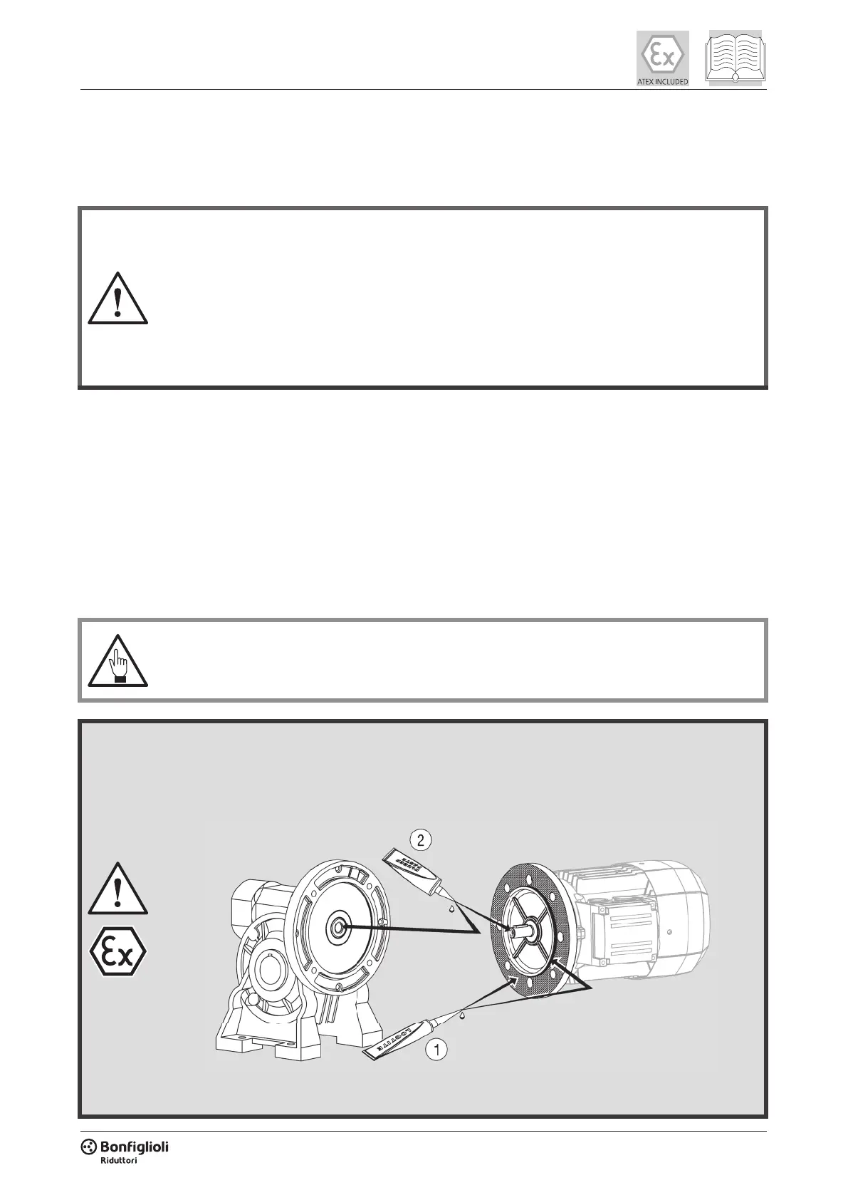
• Apply a layer of sealant such as Loctite 510 (or a product with similar properties and application range)
to the motor/gearbox coupling anges, to the alignment ring and the frontal mating surfaces as shown in
the gure below.
1. Apply Loctite 510 to the at surface of the ange and to the alignment ring.
2. Apply Klüberpaste 46MR401 to the inside of the gearbox input shaft and to the motor shaft.
 Loading...