61 / 64
IOM Manual VF-W_ATEXgb - Translation of original instructions in Italian - Rev 03_0 - 30/09/16
7.2 REMOVING A GEARBOX WITH HOLLOW OUTPUT SHAFT WITH KEYWAY
●
Remove the device that secures the gear unit axially.
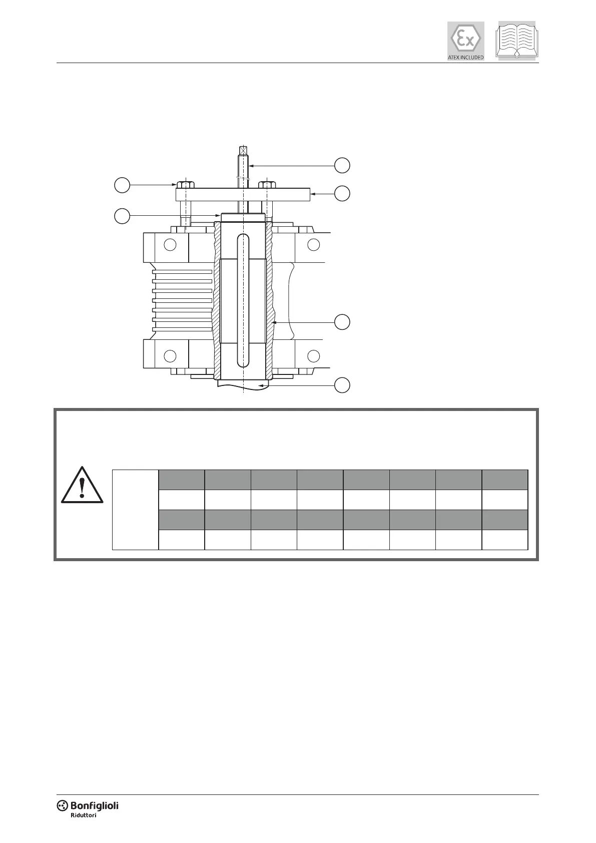
The machine’s shaft can be extracted directly in-situ using a hydraulic device, or by using the device
shown in the gure below:
4
3
6
2
5
1. Machine shaft
2. Hollow shaft
3. Threaded rod (not supplied)
4. Bolts (not supplied)
5. Thrust ring (not supplied)
6. Torque plate (not supplied)
During the extraction process observe the maximum thrust values specied in the table below and
take care to avoid knocks or misalignment.
(tab 10)
Maximum
thrust force
[N]
VF 27 VF 30 VF 44 VF 49 W 63 W 75 W 86 W 110
300 850 1250 1700 2500 3100 3500 4000
VF 130 VF 130 FR VF 150 VF 150 FR VF 185 VF 185 FR VF 210 VF 250
6900 12500 8000 17500 9750 19000 17250 26000
 Loading...