224
G
A
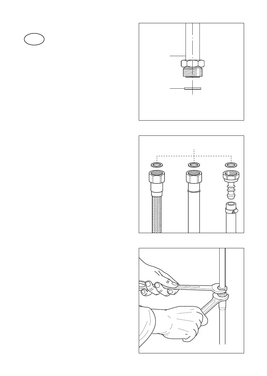
Fig. 9.7
a
G
b c
Fig. 9.8
C) GAS CONNECTION
Cat: II 2E+3+
The fitting (fig. 9.7) is made up of:
A- Gas train terminal tting (rh or lh)
G- Sealing gasket
For gases supplied by a pipe (natural
gas, G20/G25), the connection can be
made using one of the following:
• a rigid pipe with screw-nut;
• a metal corrugated exible hose
according to NF D 36-121 (g. 9.8a);
• a exible hose with mechanical ferrule
according to NF D 36-103 or D 36-100
(g. 9.8b);
For butane (G30) / propane (G31)
distributed by cylinder or tank, the
connection is made using one of the
following:
• a rigid pipe with screw-nut;
• a metal corrugated exible hose
according to NF D 36-125 (g. 9.8a);
• a exible hose with mechanical ferrule
according to NF D 36-112 (g. 9.8b);
• Only for the appliances which
cannot be built-in (classe 1) et
only for butane-propane delivered
in mobile containers: by tting the
proper hose holder (not supplied with
the appliance), interposing a sealing
gasket, and using a suitable exible
hose according to XP D 36-110 with
an internal diameter of 6 mm (g.
8.8c); make sure that the exible hose
is pushed over the hose connector to
the full depth, and secured with a hose
clamp (not supplied);
For Butane (G30)/Propane (G31) a gas
pressure regulator, according to the
Standard NF EN 13785, can be used as
main gas shutoff valve to stop the gas
supply when the appliance is not used.
Fig. 9.9
 Loading...