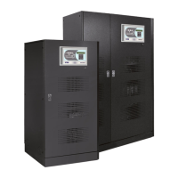
Installation and start-up of INGENIO PLUS UPS 30÷40 kVA
Installazione e avviamento INGENIO PLUS UPS 30÷40 kVA
4 OMS02082 REV. D
4.5.4 Spegnimento remoto (EPO) OPTIONAL ........................................................ 80
4.5.5 Contatto ausiliario sezionatore di batteria .................................................... 80
4.5.6 Contatto ausiliario Generatore Diesel OPTIONAL ........................................ 81
4.6 INTERFACCE SERIALI ........................................................................................... 81
4.7 COLLEGAMENTO SCHEDA RELÈ (OPZIONALE) ................................................. 82
5
AVVIAMENTO E ARRESTO ............................................................. 83
5.1 VERIFICHE PRELIMINARI ...................................................................................... 83
5.2 PROCEDURA DI AVVIAMENTO ............................................................................. 84
5.3 RICERCA GUASTI DI BASE ................................................................................... 86
5.4 PROCEDURA DI ARRESTO .................................................................................... 86
5.5 PROCEDURA DI TRASFERIMENTO SU BYPASS MANUALE .............................. 87
5.6 RIAVVIO DA BYPASS MANUALE .......................................................................... 88
Index of pictures / Indice delle figure
Picture 1 – Rating plate of INGENIO PLUS 30÷40 kVA ............................................................................. 10
Picture 2 – Handling of the INGENIO PLUS UPS 30÷40 kVA ................................................................... 18
Picture 3 – Base plan .................................................................................................................................. 20
Picture 4 – Overall dimensions ................................................................................................................... 21
Picture 5 – Minimun distances from the walls ............................................................................................ 21
Picture 6 – Terminal board INGENIO PLUS 30 kVA .................................................................................. 30
Picture 7 – Terminal board INGENIO PLUS 40 kVA .................................................................................. 31
Picture 8 – Cabling of BCB fuse holder ...................................................................................................... 33
Picture 9 - Trays 60 x9Ah 12V battery lateral view .................................................................................... 34
Picture 10 – Tray 60 x 9Ah 12V battery top view ....................................................................................... 34
Picture 11 - 60 x9Ah 12V battery connection tray top view ....................................................................... 35
Picture 12- 60 x 9Ah 12V battery connection tray front view..................................................................... 35
Picture 13 - Trays 60 x 12Ah 12V battery lateral view .............................................................................. 36
Picture 14 – Tray 60 x 12Ah 12V battery top view ..................................................................................... 36
Picture 15 – 60 x 12Ah 12V battery connection tray top view ................................................................... 37
Picture 16 - 60 x12Ah 12V battery connection tray front view................................................................... 37
Picture 17 – Position of the serial interfaces of INGENIO PLUS 30÷40 kVA ............................................. 39
Picture 18 – Relay card terminals ............................................................................................................... 40
Figura 1 – Targhetta caratteristiche INGENIO PLUS 30÷40 kVA .............................................................. 52
Figura 2 – Movimentazione UPS INGENIO PLUS 30÷40 kVA .................................................................. 60
Figura 3 – Pianta di base ............................................................................................................................ 62
Figura 4 – Dimensioni di ingombro ............................................................................................................. 63
 Loading...