Electrical diagram
830 ES – 6 720 644 936 (2021/08)
64
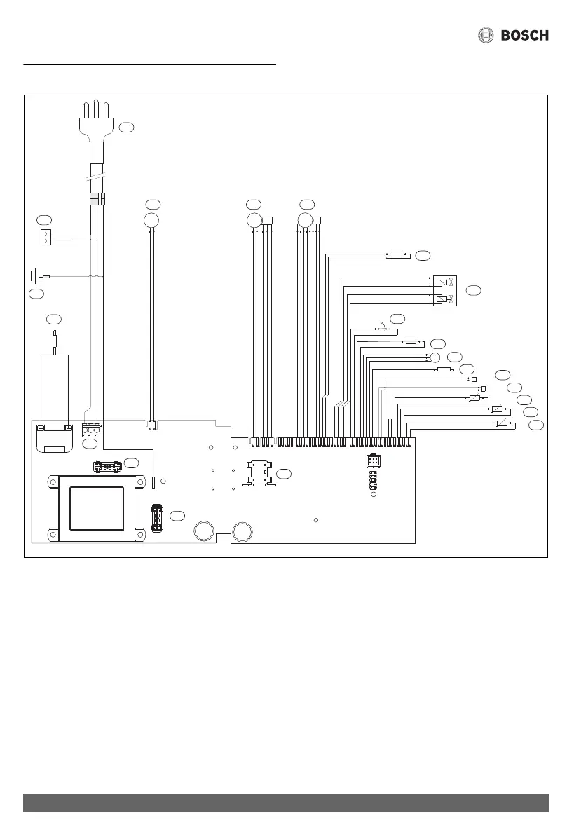
10 Electrical diagram
Fig. 63 Electrical scheme
[1] Intlet water temperature sensor
[2] Outlet water temperature sensor
[3] Backflow temperature sensor
[4] Cascading output connection
[5] Cascading input connection
[6] Ionization sensor
[7] Water flow sensor
[8] Flue gas limiter
[9] Heat exchanger overheat sensor (ECO)
[10] Gas valve
[11] Jumper resistance
[12] Water valve
[13] Primary fan
[14] ON/OFF switch
[15] Secondary fan
[16] AC plug
[17] Main connection
[18] Ignition electrodes
[19] Ground post
[20] Antifreeze kit connection
[21] Fuse
[22] Fuse
20 ... 120 ... 1
16 ... 116 ... 1
JP5
JP6
JP7
JP8
JP2
M
PS
MM
E
FS
T=104°C
T=220°F
Casc.
input
Casc.
output
2
1
4
5
6
7
9
10
11
12
13
15
16
20
19
18
21
22
17
14
8
Back flow
3
6720608158-92.1AL
T=110°C
T=230°F