ACS 653, ACS 663 Service Manual
SP00D00624 2021-04-08Robert Bosch GmbH
99
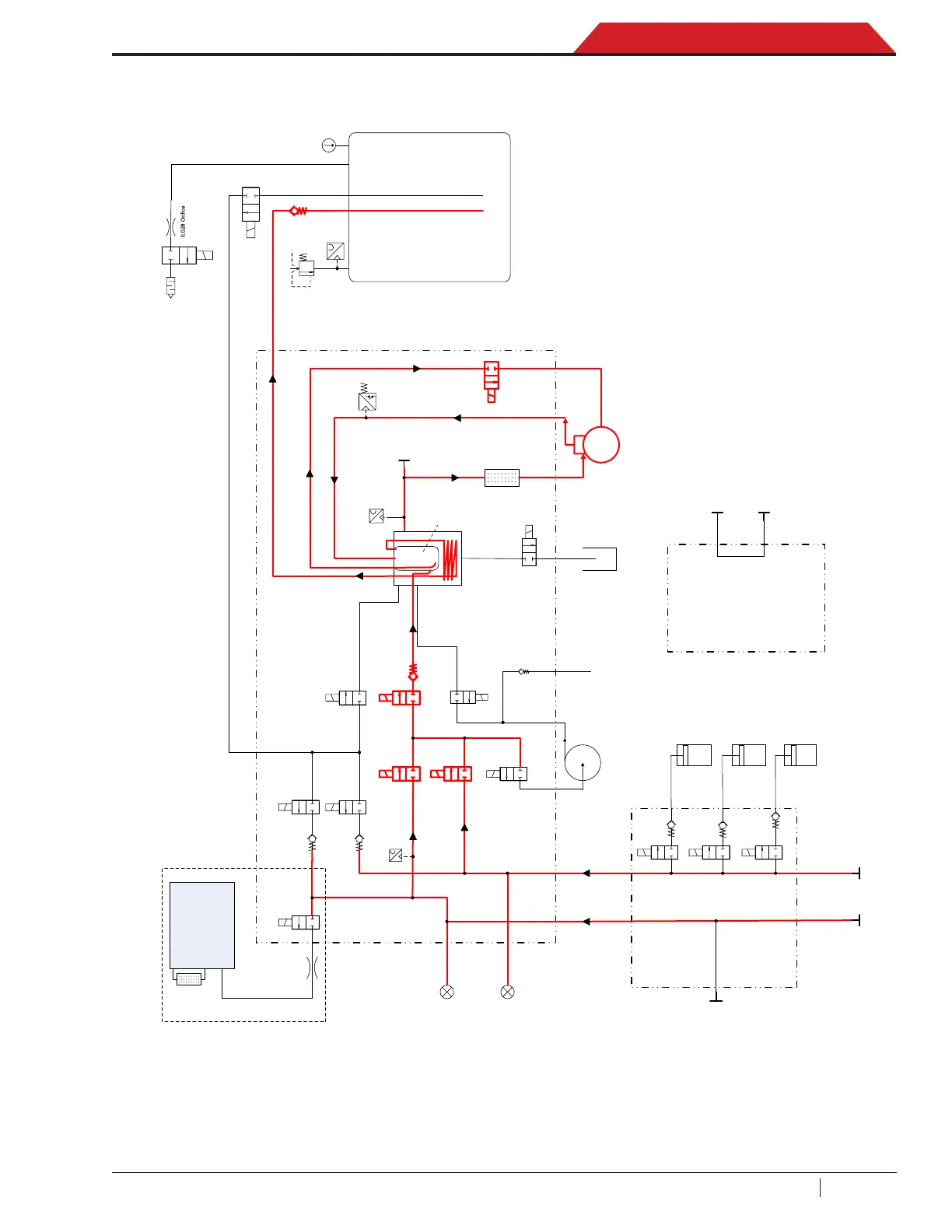
Plumbing and Mechanical
During the Tank Fill process the compressor, fan, HS and LS inlet solenoids, recover solenoid and oil return solenoid
are activated (see application chart). The output state of the recovery solenoid is controlled to maintain 2.4 bar
(35 psi) in the accumulator. When the ISV reaches the “target” weight, all components are deactivated.
Low Side
Service Hose
Vacuum Pump
Compressor
Oil 1 Inject
Bottle
Oil Drain
Bottle
High Side
Service Hose
Injection
Manifold
Accumulator
Transducer
Deep Recover
Solenoid
HS
Gauge
Vacuum Pump
Exhaust
Filter/Drier
High Pressure
Cutout Swtich
Main Manifold
Pump Exhaust
Check Valve
Oil Ret urn
Solenoid
LS Charge
Solenoid
LS Charge
Check Valve
HS Charge
Solenoid
HS Charge
Check Valve
Recycle
Solenoid
Recover Check
Valve
Recover
Solenoid
Heat Exchanger /
System Oil
Separator
Compressor Oil
Separator
LS Inlet
Solenoid
HS Inlet
Solenoid
Vacuum
Solenoid
Oil Inject 1
Solenoid
Oil Inject 1
Check Valve
Oil Drain
Solenoid
Service Port
ID Orifice
Refrigerant
Identifier
RI Filter
Oil Inject 2
Solenoid
Oil Inject 2
Check Valve
Dye Inject
Solenoid
Dye Inject
Check Valve
Oil 2 Inject
Bottle
Dye Inject
Bottle
LS
Gauge
ID Solenoid
Low Side
Transducer
Air Purge
Solenoid
Temp.
Sensor
Air
Diffuser
Contamination
Port
Vapor
Liquid
Internal
Tank
Tank Liquid
Solenoid
Pressure
Relief
ISV Pressure
Transducer
Vapor
Check Valve
Low Side
Storage Port
High Side
Storage Port
Flush Manifold
RI variants only

 Loading...