Do you have a question about the Bosch T1 Alternator and is the answer not in the manual?
Use only specified tools for repairs to avoid damage and injury.
Capacitors retain charge; discharge may ignite combustible liquids.
Use protective gloves or creams for oils/greases and wash hands after work.
Use compressed air regulated to 4 Bar (60 PSI) for cleaning parts.
Avoid fire, flames, sparks; dry parts thoroughly to prevent gas explosions.
Defines electrical parameters like resistance, voltage, and current for testing.
Details mechanical tolerances such as air gap, eccentricity, and brush projection.
Specifies torque values for various fasteners during assembly and disassembly.
Lists essential test equipment required for alternator diagnostics and repair.
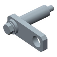
Details specialized tools needed for specific alternator disassembly and assembly procedures.
Lists required lubricants and adhesives for alternator maintenance and repair.
Specifies the precise amounts of grease and lubricants for key components.
Procedure for removing the rear cover of the alternator.
Steps to safely remove the voltage regulator from the collector ring end shield.
Detailed instructions for measuring and replacing worn carbon brushes.
Procedure for testing and removing the noise suppression capacitor.
Method for removing the pulley and fan from the alternator shaft.
Steps to separate the drive end shield from the collector end shield.
Tests to verify the functionality of the rectifier assembly.
Procedure for removing and testing the stator assembly's resistance and insulation.
Steps for the removal of the rectifier assembly from the collector end shield.
Procedure for testing and removing the dampening resistor incorporated in the W terminal.
Instructions for removing the bearing and seal from the collector end shield.
Steps to press out the sliding bushing from the collector end shield.
Procedure for pressing the rotor out of the drive end shield.
Instructions for removing the bearing and seal from the drive end shield.
Steps to remove the inner bearing race from the rotor shaft.
Tests for rotor resistance, insulation, and concentricity.
Procedure for removing and replacing the alternator collector rings.
Steps for assembling the collector rings onto the rotor shaft.
Procedure for installing the bearing and retaining screws in the drive end shield.
Instructions for installing bearings, seals, and bushings into the collector end shield.
Steps for preparing and mounting the rectifier assembly.
Procedure for soldering stator leads to the rectifier assembly.
Steps for installing the rotor and drive end shield assembly with feeler gauges.
Procedure for installing the voltage regulator and suppression capacitor.
Overview of the two main functional testing categories: Power Output and Voltage Trace.
Procedure for testing the alternator's ability to produce rated current and voltage.
Analysis of alternator output waveforms against known patterns to identify faults.
| Brand | Bosch |
|---|---|
| Model | T1 Alternator |
| Category | Industrial Equipment |
| Language | English |





 Loading...