Repair and Testing Instructions for T1 Page 18
Alternator 0120 689 552 Edition 001
All rights rest with Robert Bosch Corp, including patent rights. All rights of use of reproduction and publication rest with R. B. Corp.
UA/ASV 04.12.98 T1ALTFinal.DOC
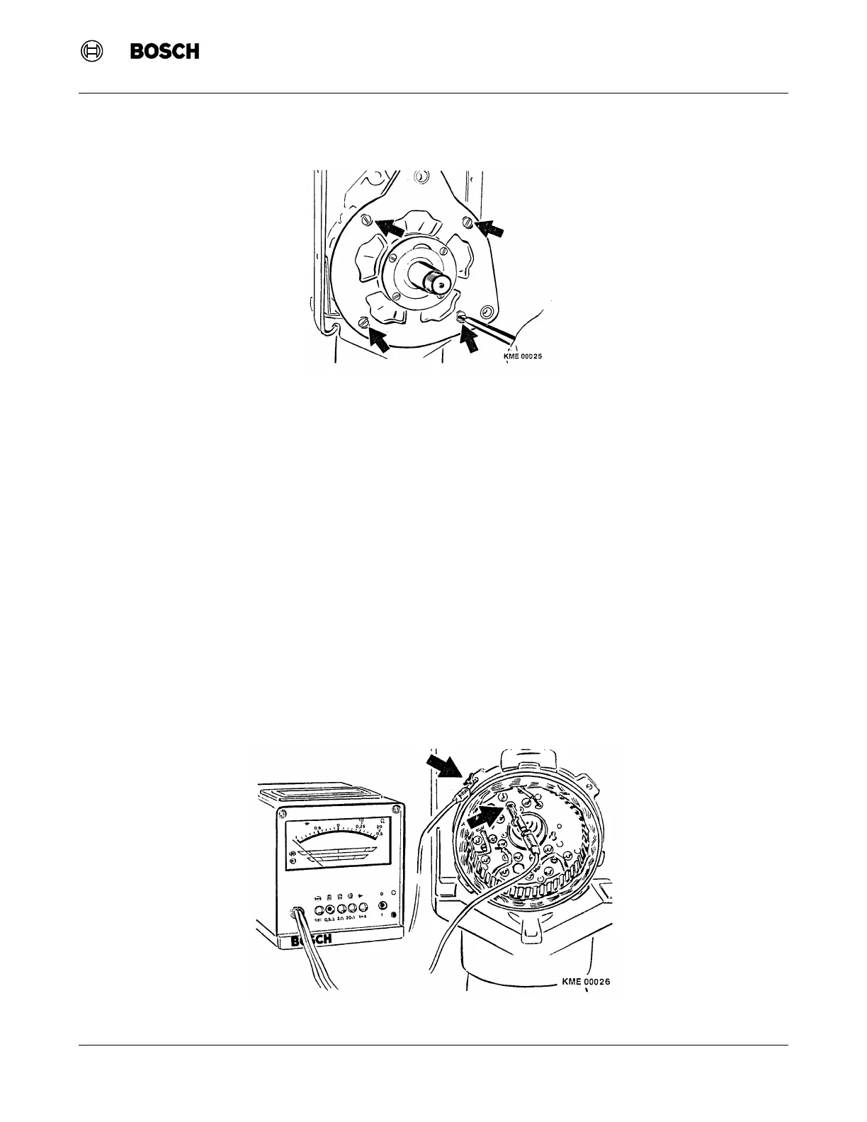
2. Slide the drive end shield and rotor out of the collector end shield.
9.6 Rectifier Assembly Testing
Note: The following testing of the rectifier is to be performed with the rectifier assembly installed and wired in to
the stator.
1. With the rectifier assembly still installed in the collector end shield, testing of the rectifier is to be
performed.
a. Using tester WPG 012.00 (Bosch Number 0 684 201 200) (Figure 11)
i) Connect the negative (black) lead of the tester to the collector end shield and the positive (red) lead
to each of the stator connection solder joints.
ii) Connect the positive (red) lead of the tester to the B+ Terminal and the negative (black) lead to
each of the stator connection solder joints.
iii) Connect the positive (red) lead of the tester to the D+ Terminal and the negative (black) lead to
each of the stator connection solder joints.
The rectifier assembly is reusable if the tester remains in green zone. If the rectifier assembly fails any test, one
or more of the diodes are defective and the whole assembly must be replaced.
Figure 10 Drive End Shield Removal
Figure 11 Testing of Rectifier Assembly
 Loading...