© 2015 Bosch Security Systems, Inc. F.01U.311.091 | 03 | 2015.09
Bosch Security Systems, Inc. product manufacturing dates
Use the serial number located on the product label and refer to the Bosch Security
Systems, Inc. website at http://www.boschsecurity.com/datecodes/.
Copyright
Use the serial number located on the product label and refer to the Bosch Security
Systems, Inc. website at http://www.boschsecurity.com/datecodes/.
Trademarks
All hardware and software product names used in this document are likely to be registered
trademarks and must be treated accordingly.
8 |
Specifications
Dimensions 79 mm x 128 mm x 38 mm (3.11 in x 5.03 in x 1.50 in)
Voltage output
(operating)
12 VDC nominal (Special application)
Standby battery
current
requirements
*Battery input: B465: Idle 150 mA; Alarm 230 mA
Alarm: B465 with B440/B441/B442/B443 = 180 mA
24 VDC input
current
requirements
*24 VDC input: B465: Idle 120 mA; Alarm 160 mA
USB cable USB cable (Type A to A male-to-male) - not supplied.
Use a Bosch supported cable such as the B99 cable
(F01U278853)
Compatible
transformers
D1640, 120 VAC input, 16.5 VAC, 40 VA output Class 2
plug-in
D1640-CA 120 VAC input, 16.5 VAC, 40 VA output Class
2 plug-in
D1640-120WI, 120 VAC input, 16.5 VAC, 40 VA output
Class 2 wire-in
Compatible
digital dialer
formats
Contact ID
Pulse 3/1, Pulse 4/2
SIA (SIA8, SIA20)
Compatible
receivers
D6600/D6100IPv6/D6100i
Compatible
enclosures
B10/B10R Medium Control Panel Enclosure
B11/B11R Small Control Panel Enclosure
D8103 Enclosure
Compatible
module
B46 module (must use supporting B46 cable to connect
to the B465)
Relative
humidity
Up to 93% non-condensing
Temperature
(operating)
0° to +49° C (+32° to 120° F)
*Refer to the Standby battery requirements and calculations section in the
B465 Installation and Operation Guide for the current draw requirements of
other system components
7 |
Certifications
Region Certification
US FCC Part 15 Class B
NIST FIPS 197 AES Certification (IP Communications)
California State Fire Marshall (CSFM)
UL 365 – Police Station Connected Burglar Alarm Units and
Systems
UL 609 – Local Burglar Alarm Units and Systems
UL 864 – Control Units and Accessories for Fire Alarm Systems
UL 985 – Household Fire Warning System Units
UL 1023 – Household Burglar Alarm System Units
UL 1076 – Proprietary Burglar Alarm Units and Systems
UL 1610 – Central Station Burglar Alarm Units
Canada CAN/ULC S303 – Local Burglar Alarm Units and Systems
CAN/ULC S304 – Signal Receiving Centre and Premise Alarm
Control Units
ULC - S545 – Residential Fire Warning System Control Units
ULC – ORD C1023 – Household Burglar Alarm System Units
ULC – ORD C1076 – Proprietary Burglar Alarm Units and Systems
ICES – 003 – Digital Apparatus
Bosch Security Systems, Inc.
130 Perinton Parkway
Fairport, NY 14450
USA
www.boschsecurity.com
Bosch Sicherheitssysteme GmbH
Robert-Bosch-Ring 5
85630 Grasbrunn
Germany
2.11 |
Earth ground wiring
Connect the system to earth ground before making other
connections. Doing so prevents damage from electrostatic
discharges or other transient electrical surges. Use a
recommended earth ground reference such as a grounding
rod, or a cold water pipe. Make the connection using 14
AWG (1.8 mm) to 16 AWG (1.5 mm) wire. Refer to the
B465
Installation and Operation Guide (P/N: F01U311207).
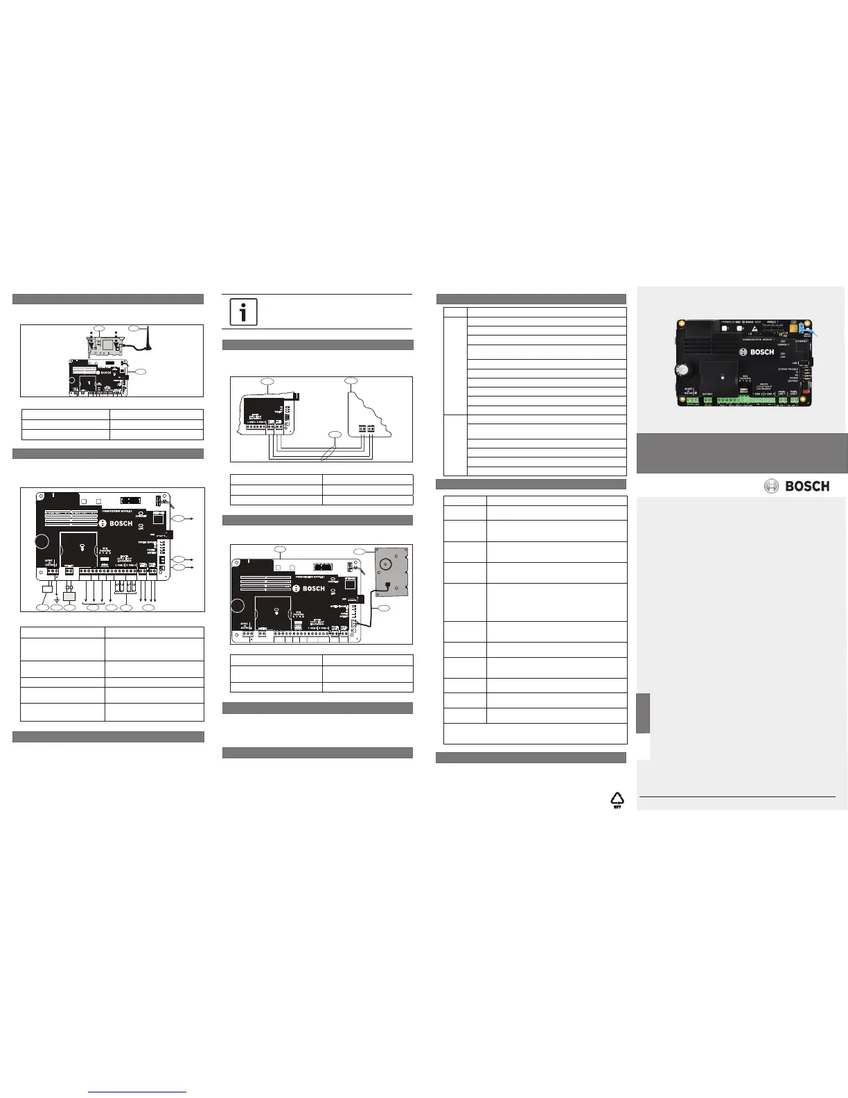
2.9 | Insert the cellular module (optional)
Insert the cellular module into the slot of the B465 until the
module “clicks” into place. Refer to Figure 2.9.
Callout ― Description Callout ― Description
1 ― B44x cellular module 3 ― B465
2 ― Antenna
Figure 2.9: Insert the cellular communication module
Callout ― Description Callout ― Description
1 ― RJ 45 Ethernet
connection to central station
6 ― 12V AUX/COM terminals
(optional output power source,
Special Application 9.9 - 13.8 V)
2 ― External Annunciator
terminal (connected to B46)
7 ― Programmable output relays
(Relay 1, Relay 2, Relay 3)
3 ― To tamper switch 8 ― Battery (7-18 Ah)
4 ― Phone Line 1/2 to control
panel terminals
9 ― To earth ground
5 ― EOL input loop
10 ―
16.5 VAC or 24 VDC power
supply input terminals
4 |
LED descriptions
The B465 and B46 modules include on-board LEDs to assist
with troubleshooting issues as well as communication status.
For detailed information on all LED descriptions, refer to the
B465 Installation and Operation Guide (P/N: F01U311207).
You can configure the B465 using USB. For information on
configuring the B465, refer to the B465 Installation and Operation
Guide (P/N: F01U311207).
3 |
Configuration
Callout ― Description Callout ― Description
1 ― B465 module 3 ― Intrusion/Fire control panel
2 ― Phone wiring connection
Callout ― Description Callout ― Description
1 ― B465 module 3 ― B46 wiring harness (P/N:
F01U310747)
2 ― B46 module
2.12 | Wire to the control panel
Use supporting wiring when connecting a B465 to a intrusion/
fire control panel in order to establish communication. Refer to
Figure 2.11.
Figure 2.11: System wiring
TMPR
BAT
REMOTE
INTERFACE
1 COM 2
PNL LINE 2
3 COM 4
PNL LINE 1
RX
AC
PANEL
LINE 2
3 COM 41 COM 2
PANEL
LINE 1
BATTERY
AC
RX
INPUTS
2.2 k End of
Line Resistors
1
T R
T R
2
3
2.13 | Wire to B46 (optional)
Use supporting B46 cable to connect to the B465. Refer to
Figure 2.12.
Figure 2.12: B46 wiring
TMPR
BAT
ETHERNET
EXTERNAL
ANNUNC
X
MODULE 1
Y
MODULE
RELEASE
1 COM 23 COM 4
T R
PNL LINE 1
C NO
RELAY 2
+
-
BATTERY
16.5VAC
NC C NO
RELAY 1
TRBL
TX
RX
PWR
PANEL
LINE 2
USB
ETHERNET
100BASE-T
LINK
COMMUNICATION MODULE 1
3 COM 41 COM 2
R Y G B
SDI2
Device Bus
BATTERY
PANEL
LINE 1
BATTERY
POWER
RX
TX
SYSTEM TROUBLE
INPUTS
2.2 k End of
Line Resistors
C NO
RELAY 3
12V
AUX COM
T R
PNL LINE 2
24 VDC
or
16.5 VAC
1
2
3
NOTICE!
The D8004 is required for any Commercial Fire
installations that use a plug-in transformer.
en Quick Start Guide
Conettix Universal Dual Path
Communictor
B465

 Loading...


