© 2010 Bosch Security Systems, Inc. 4998153065 | 08 | 2010.10 | 1
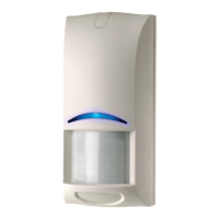
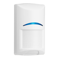
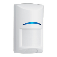
Blue Line P1
ISM-BLP1-P
UL
Use only a Listed limited-power source.
ISM-BLP1 è certifi cato IMQ – Sistemi di sicurezza al primo
livello di prestazione. La certifi cazione IMQ – Sistemi di
sicurezza decade nel caso di installazione del rilevatore con
gli snodi opzionali B328, B338, B335.
SBSC larmklass 3, miljöklass 2
SELV
Connect all wiring to a safety extra-low voltage (SELV) circuit only.
Anslut allt kablage endast till en säkerhetskrets med extra låg spänning (SELV).
Sluit alle bedrading uitsluitend aan op een circuit met een extra lage veiligheidsspanning.
Prenez soin de connecter tous les câbles à un circuit à très basse tension de sécurité (TBTS).
Alle Drähte sind ohne Ausnahme an Niederspannung anzuschließen.
Collegare tutti i cavi esclusivamente a un circuito SELV (circuito di sicurezza a bassissima tensione).
Ligue todas as cablagens apenas a um circuito de segurança de tensão extra baixa (SELV).
Conecte el cableado únicamente a un circuito de seguridad para voltajes muy bajos (SELV).
仅限将所有的线路与安全极低电压(SELV)电路连接。
-29°C to +49°C (-20°F to +120°F )
For UL Listed installations, the temperature range is 0°C to +49°C
(+32°F to +120°F)
Pour les installations certifi ées NFA2P, Température de fonctionnement
-10°C à +55°C
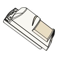
107 mm
(4.2 in.)
61 mm
(2.4 in.)
48 mm
(1.9 in.)
EN CLC/TS 50131-2-2 Grade 2
EN 50130-5 Environmental Class II
IP30 IK04 (EN 60529, EN 50102)
≤ 13 kg (30 lb)
The pet immunity feature was not tested by UL.
CNPP Test Report 470 3 008 01 0001
Certifi cation NF A2P Type 2
Attestation NFA2P Type 2
2620002631 delivrée par
CNMIS SAS 75017 PARIS
CNPP Certifi cation 27950 St Marcel
BE: INCERT: B509-0009
Current Draw: 10 mA @ 12 VDC
Standby Power: No internal standby battery.
For UL Listed product installations, provide 4 h (60
mAh) standby power from the control unit or by a UL
Listed burglary power supply.
Humidity: 0 to 95% non-condensing (0 to 85% UL installations)
Strömförbrukning: 15 mA @ 12 VDC, vid larm 22 mA
Vilolägesförbrukning: Inget internt vilolägesbatteri.
Relativ luftfuktighet: 0 till 95 % luftfuktighet, icke-kondenserande
Stroomverbruik: 10 mA op 12 VDC
Relatieve vochtigheid: 0 tot 95% niet condenserend
Consommation :
10 mA à 12 Vcc en veille / en alarme source limitée
en puissance, ondulation résiduelle 1 V
Humidité : de 0 à 95% sans condensation
Stromaufnahme: 10 mA bei 12 V DC
Luftfeuchtigkeit: 0 bis 95%, nicht-kondensierend
Assorbimento di corrente: 10 mA @ 12 V—
Umidità: Da 0 a 95% senza condensa
Consumo: 10 mA a 12 VCC
Humidade: 0 a 95% sem condensação
Consumo de corriente: 10 mA a 12 Vcc
Humedad: de 0 a 95% sin condensación
最大电流: 10 毫安 @ 12伏直流
湿度: 0至95%非冷凝