Do you have a question about the Bosch Control Air M and is the answer not in the manual?
Explains the meaning of symbols used in the document.
Details hazardous situations and precautions to prevent injury or death.
Describes the Human-Machine Interface for DDC Control Air 5600.
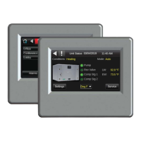
Details the touchscreen module for connecting to the Control Air 5600.
Explains the mobile app interface for controllers via Android tablets.
Provides the recommended wiring connections for the Control Air M.
Details cable type, conductor, length, and insulation for Rnet wiring.
Connects via tablet to the controller's local access port for operations.
Step-by-step guide for wiring and physically mounting the Control Air M/M+ module.
Provides guidance on connecting the module or tablet to the DDC controller.
Explains the password entry process for accessing protected screens.
Describes the Alarm screen for viewing events and status.
Details how to view trends for points with trending enabled.
Specifies the required USB flash drive format (FAT, FAT16, FAT32) for updates.
Step-by-step process for updating the device's firmware via USB.
Instructions for creating a reset.dat file to restore factory defaults.
Details FCC and CE compliance statements and notices.
The main screen showing unit status, diagnostics, and navigation options.
Access point for configuring unit settings, device settings, and alarms.
Enables adjustment or reset of settings on the Control Air M/M+ module.
Allows adjustment of heat pump unit alarm settings and trip limits.
View and adjust pump parameters like continuous run and start counters.
View entering/leaving water temps and setpoints.
Adjust setpoints and differentials for heating, cooling, and auto changeover.
View, add, edit, or delete BACnet schedules for the controller.
Configure compressor rotation and view demand/rotation frequency.
Access for qualified technicians to adjust, reset, and troubleshoot unit settings.
View actual state of points for cooling and heating operations.
Displays UPM status and allows resetting the UPM board.
Access software version, controller info, and troubleshooting tips.
| Brand | Bosch |
|---|---|
| Model | Control Air M |
| Category | Touchscreen |
| Language | English |