Installation & Operation Manual Control Air M/M+ Water to Water Applications | 3
BTC 469503103 A | 02.2019
Data subject to change
Table of Contents
1 Key to Symbols and Safety Instructions 4
1.1 Key to Symbols 4
1.2 Safety Warnings 4
2 Introduction 5
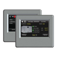
2.1 The Control Air M/M+ Interfaces 5
2.2 The Control Air M/M+ Module 5
2.3 Virtual Control Air M/M+ (Equipment Touch (OEM) APP) 5
3 Specifi cations 6
4 Physical Dimensions 7
5 Wiring 8
5.1 Recommended Wiring Scheme 8
5.2 Rnet Wiring Specifi cations 8
6 Connection 8
6.1 Communicate Using a Tablet Through Virtual Control Air M and M+ 8
6.2 To Wire and Mount the Control Air M/M+ 8
6.3 Additional Information on Connecting Control Air
M/M+ to a Controller 9
7 How to Navigate Screens in Control Air M/M+ 11
7.1 Login 11
7.2 Alarms 11
7.3 Trends 11
8 To Update the Control Air M/M+’s Firmware 12
8.1 Prerequisite 12
8.2 To Update the Firmware 12
8.3 Resetting the Control Air M/M+ 12
8.4 Compliance 13
9 The Control Air M and M+ Screens 14
9.1 Units Status Screen/Home Page 14
9.2 Settings Screen 14
9.2.1 Unit Settings Screen 14
9.2.2 Device Settings Screen 16
9.2.2.1 Controller Screen 16
9.2.2.1.1 Set Time and Date 16
9.2.2.1.2 Communication 16
9.2.2.1.3 Router 17
9.2.2.1.4 IP 17
9.2.2.1.5 Time Master 17
9.2.2.2 Touchscreen Screen 18
9.2.3 Alarms Settings Screen 18
9.2.4 Pumps 19
9.2.5 Temperature 19
9.2.6 Setpoints 19
9.2.7 Schedule Screen 20
9.2.8 Lead/Lag Screen 22
9.3 Service Screen 22
9.3.1 Heat/Cool Screen 23
9.3.2 UPM Status Screen 23
9.3.3 Help Screen 24