8
|
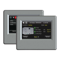
Control Air M/M+ Water to Water Applications Installation & Operation Manual
02.2019 | BTC 469503103 AData subject to change
5 Wiring
The Control Air M communicates through a Rnet connection. The Control
Air M is intended for use with a single WSHP. It can be wired using the
instructions in section 6. The Control Air M+ communicates through a
BACnet MS/TP connection. The Control Air M+ is intended for use with up
to 50 WSHP's on an exisiting network.
5.1 Recommended Wiring Scheme
Connect this wire: To this terminal on the Control Air M:
Red 24 VAC (R)
Black 24 VAC (C)
White Rnet+
Blue Rnet-
Table 2 Power Wiring
2-conductor wire 18 AWG for distances up to 100 feet. All transformer
secondaries must be grounded. Wiring connections must be in
accordance with NEC and local codes. All wiring and mounting screws
must be fi eld supplied.
5.2 Rnet Wiring Specifi cations
NOTICE:
Use the specified type of wire and cable for maximum
signal integrity.
Description Value
Cable
4 conductor, unshielded, or unshielded
CMP, plenum rated cable
Conductor 22 AWG (7x0096) bare copper
Maximum length 500 feet (152 meters)
Recommended coloring Jacket: White
UL temperature 32–167°F (0–75°C)
Voltage Limited Listing 300 VAC, power UL: NEC CL2P, or better
Insulation Low-smoke PVC (or equivalent)
Color Code Black, white, green, red
Shielding
If shielded, Aluminum/Mylar shield
(100% coverage) with TC drain wire
Table 3
6 Connection
6.1 Communicate Using a Tablet Through Virtual Control Air M and M+
In lieu of using the module to interface with the controller, a connection
may be established at the local access port of the controller to perform
test and balance operations or to make changes to any device on the network.
6.2 To Wire and Mount the Control Air M/M+
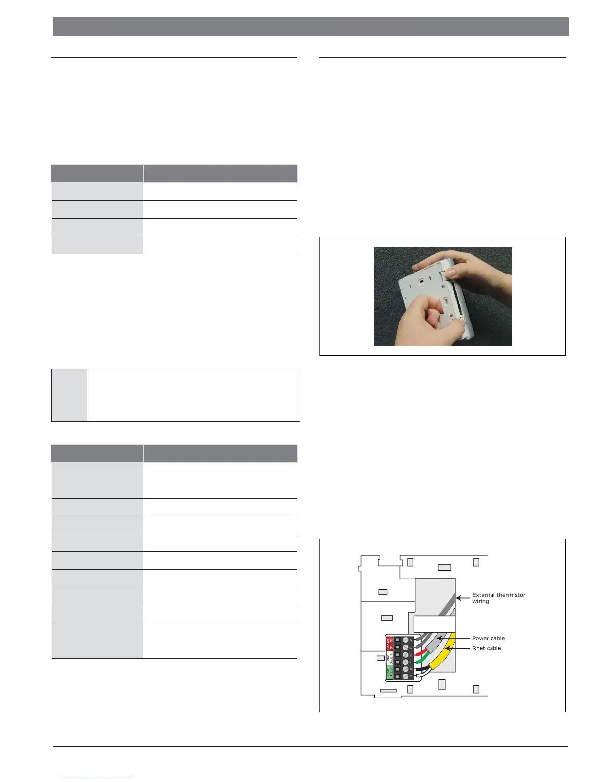
1. Remove the backplate from the Control Air M/M+
a. Hold the Control Air M/M+ as shown in the picture below.
b. While fi rmly pressing the 2 tabs on top of the Control Air M/
M+, pull on the backplate with your index fi nger until the
backplate releases from the Control Air M/M+.
Figure 5
2. Pull the communication cable, power cable, and external
thermistor wiring (if applicable) through the large hole in the center
of the backplate.
3. Partially cut, then bend and pull off the outer jacket of the Rnet
cable(s). Do not nick the individual wire insulation.
4. If wiring 1 cable to the Control Air M/M+, cut the shield wire off at
the outer jacket, then wrap the cable with tape at the outer jacket
to cover the end of the shield wire. If wiring 2 cables in a daisy-
chain confi guration, twist together the shield wires, then wrap the
shield wires with tape.
5. Strip about 0.25 inch (0.6 cm) insulation from the end of each
wire.
6. Connect wiring to the Control Air M/M+ as shown in Figure 6.
Figure 6