Graphic Keypads Installer Reference Guide
3
Bosch Security Systems 03/16 Graphic Keypads BIRG FTR1.0
The Solution Graphic Keypad’s décor-friendly white plastic housing and stylish curved face blends with the most dis-
cerning of interior designs and can be used with or without the hinged door according to individual customer taste
or requirements.
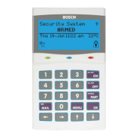
All system programmable features and options are displayed in full text on the
keypad allowing the system to be programmed and configured without refer-
ring to the manual. Different models are available including versions with built-
in Smart Card readers and Wi-Fi connectivity.
Keypads include red, green and blue indicators which are used to show area /
door status and the 20 buttons with blue backlighting make it easy to operate
in all lighting conditions. Refer to the panel Installer Reference Guide for more
information on keypad options and panel programming.
Solution 6000 Keypad Compatibility
Keypad Model Panel Version Keypads Supported
CP700B All versions Up to 16
CP710B All versions Up to 16
CP722B All versions Up to 16
CP732B All versions Up to 16
CP741B with Wi-Fi 2.25 or higher 1 Only (address 1)
Table 1: Keypad Compatibility
Keypad Addressing
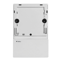
Each keypad fitted to the system must be assigned a unique address on the LAN. For convenience the address dip
switch configuration table shown below is also provided on the rear of the plastic keypad housing.
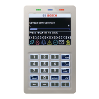
Wi-Fi enabled keypads are factory set to address 1 and cannot be changed. Other keypads should be set to an ad-
Solution - Graphic Keypads
Figure 1: Wi-Fi Enabled Graphic Keypad
dress other than 1 when a Wi-Fi keypad is being used.
Only 1 x Wi-Fi enabled keypad is supported per system.
Dip Switch 5 has been provided on selected keypads to
allow easy termination of the RS485 LAN at the keypad if
required.
DIP Switch Address Select
4 5
SW5=LAN Term
Only 1 x Keypad can be assigned to each address.
All Keypads are supplied from the factory set to
address 1. You must power cycle the panel or
perform a LAN scan whenever you change the
keypad address
DIP Switch Address Settings
Keypad/
Reader N
o
S1 S2 S3 S4 S5
1 Off Off Off Off
LAN Terminator Switch
2 On Off Off Off
3 Off On Off Off
4 On On Off Off
5 Off Off On Off
6 On Off On Off
7 Off On On Off
8 On On On Off
9 Off Off Off On
10 On Off Off On
11 Off On Off On
12 On On Off On
13 Off Off On On
14 On Off On On
15 Off On On On
16 On On On On
Table 2: DIP Switch Address Settings
Figure 2: Address Switch Settings