6720856749 (2016/03)CR50
Installation | 3
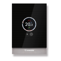
2.2 Scope of delivery
Fig. 2 Scope of delivery
[1] User interface
[2] Technical documentation
2.3 Technical data
Fig. 3 Dimensions in mm
Table 1 Technical data
2.4 Temperature sensor characteristics
Table 2 Resistance values for flow and hot water
temperature sensors
2.5 Applicability of the technical documentation
Information in the technical documentation about heat
sources, heating controllers or the BUS apply also to the
present user interface.
2.6 Additional accessories
No other BUS modules and user interfaces are possible in the
system with the CR 50.
Combination is not possible with the following products:
• FR..., FW..., TR..., TF..., TA...
3 Installation
DANGER:
Life-threatening danger from electrical shock!
▶ Before installing this product:
Disconnect the heat source and all other BUS nodes from
the mains voltage across all poles.
3.1 Installation location
This user interface is intended only for wall-mounted
installation.
Do not install in the heat source or in wet areas.
Rated voltage 8 ... 16 V DC (2-wire BUS/EMS 2
and OpenTherm)
Rated current 5 ... 23 mA (2-wire BUS/EMS 2 and
OpenTherm)
BUS interface 2-wire BUS, EMS 2, OpenTherm
Control range 5 ... 30 °C
permissible ambient
temperature
0 °C ... 50 °C
Power reserve t4 h
Protection class III
IP-Rating IP20
0010008715-001
i
i
1
2
6 720 809 984-08.1O
95
25
33
95
°C : °C : °C : °C :
8 25065 32 9043 56 3723 80 1704
14 19170 38 7174 62 3032 86 1421
20 14772 44 5730 68 2488 – –
26 11500 50 4608 74 2053 – –

 Loading...