EasyManua.ls Logo

Bosch D2071A User Manual

Bosch D2071A
28 pages
To Next Page IconTo Next Page
Page #1 background imageLoading...
Page #1 background image
D2071A
EN
Operation & Installation Guide
Fire Alarm Control Panel

Table of Contents

Questions and Answers:

Bosch D2071A Specifications

General IconGeneral
BrandBosch
ModelD2071A
CategoryControl Panel
LanguageEnglish

Summary

FCC Notice

Overview

Communicator

Describes the D2071A's built-in communicator and its reporting capabilities.

RFI and Lightning Protection

Details the D2071A's resistance to radio frequency interference and high-voltage surges.

D2071A Kit Contents

Lists the components included with the standard D2071A package.

D2071AC Kit Contents

Lists the additional components included with the D2071AC kit.

Required Materials

Lists additional parts necessary for the installation of the D2071A.

Listings and Approvals

Details the UL listings, NEC compliance, and other agency approvals for the D2071A.

Mandatory Connections

Slave Communicator Applications

Slave Application Power Requirements

Details power requirements for D2071A when used in slave communicator applications.

UL Listed Enclosure Requirements

Specifies requirements for using UL Listed enclosures for the D2071A installation.

Receiving Equipment Compatibility

Control Panel Assembly Details

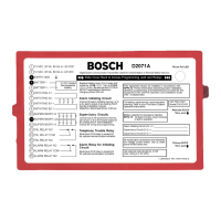
Terminal Strip Description

Describes the terminal strip and its connections for power, circuits, and relays.

Programmer Connector

Identifies the connector for the D5100 or D5200 programmer.

Enclosure Cover Access

Explains how to access the internal components via the enclosure cover.

Phone Line Trouble Buzzer Functionality

Details the function of the phone line trouble buzzer and associated LED/relay.

Phone Line Trouble LED Indicator

Mounting Tabs and Methods

Alternate Telephone Line Connection

Primary Telephone Line Connection

Phone Line Trouble Relay Installation

Initiating Circuit Alarm Relay Installation

Strain Relief Tab Usage

Installation Procedures

Earth Ground Wiring

Provides instructions for connecting earth ground wiring for different power modes.

Zone 1 Alarm Initiating Circuit

Details the Zone 1 alarm initiating circuit, including Class 'A' parameters and timers.

Supervisory Circuits (Zones 2 and 3)

Supervisory Circuit Mode 1

Describes Mode 1 configuration for supervisory circuits, not for stand-alone.

Supervisory Circuit Mode 2

Describes Mode 2 configuration for supervisory circuits, with restrictions.

Zone 1 Retard and Reset Times

Zone 1 Wiring Configuration

Supervisory Circuit Mode 3

Supervisory Circuit Mode Restrictions

Supervisory Circuits Wiring

Supervisory Circuit Class 'B' Parameters

Initiating Circuit Alarm Relay

Initiating Circuit Alarm Relay Installation

Instructions for installing the D136 relay in socket K6 for the alarm relay.

Initiating Circuit Alarm Relay Wiring

Details wiring connections for the initiating circuit alarm relay.

Phone Line Trouble Relay

Phone Line Trouble Relay Installation

Instructions for installing the D136 relay in socket K5 for the trouble relay.

Phone Line Trouble Relay Wiring

Details wiring connections for the phone line trouble relay.

Primary Power Supply

12 VAC Mode Power Supply

Details connecting a 12 VAC transformer for primary power in 12 VAC mode.

24 VDC Mode Power Supply

Secondary Power & Charging (12 VAC Mode)

Battery Installation and Types

Details battery requirements, installation, and replacement for 12 VAC mode.

Telephone Connections

Telephone Cord Installation

Instructions for connecting primary and alternate telephone lines using modular jacks.

Telephone Connection Location

Guidance on locating RJ31X or RJ38X jacks to avoid interrupting normal phone use.

Telephone Line Supervision

Explains how the D2071A monitors telephone lines for trouble conditions.

Call Routing Configuration

Telephone Company Notification

Cable Tie Installation

Screw Mounting Method

Details how to mount the D2071A using screws and mounting tabs.

D2002 Mounting Plate Usage

Explains how to use the D2002 mounting plate for installation.

Adhesive Strip Mounting Method

Details how to mount the D2071A using provided adhesive strips.

End User Instruction Label

Programming the D2071A

Navigating Programmer and Records

Explains how to navigate the D5200 programmer and program records.

Programmer Function Keys

Programmer Data Keys

Programmer Notification Tones

Editing Programmer Records

Programmer Connection Procedure

Entering the 2071 Handler

D2071A Program Modules

Editing the Program Record Options

Program Record Details

Account Number Configuration

Sets the account number for the D2071A, with default and selection options.

Transmit BFSK Format

Selects the reporting format: BFSK or fast, single-round pulsed.

DTMF Dialing Configuration

Selects between dual tone multi-frequency or pulse dialing for telephone numbers.

Primary Prefix Configuration

Selects the prefix for the primary receiver telephone number, allowing up to nine characters.

Alternate Prefix Configuration

Selects the prefix for the alternate receiver telephone number, allowing up to nine characters.

Alternate Phone Number Configuration

Selects the alternate receiver telephone number, allowing up to seven characters.

12 V Mode Selection

Enables or disables the 12 V Mode, which uses a 12 VAC transformer.

Class 'B' Supervisory Mode

Programs the mode for Class 'B' Supervisory Circuits (Zones 2 and 3).

Retard Time Programming

Programs the retard timer for the Zone 1 Alarm Initiating Circuit.

Reset Time Programming

Hours Until First Test Report

Minutes Until First Test Report

Receiver Reports Explained

Troubleshooting Guide

Phone Line Trouble Indicators

Explains the activation of the phone line trouble buzzer, LED, and relay.

Diagnosing Phone Line Trouble

Steps to identify and resolve phone line trouble conditions.

Troubleshooting Communications Failure

Procedure to confirm and resolve communications failure issues.

Trouble Zone E Report Analysis

Troubleshooting D5200 Programmer Issues

Zone Specific Problems

Trouble Zone 9 (Power Issues)

Technical Specifications

Related product manuals