EasyManua.ls Logo

Bosch DS7240V2 User Manual

Bosch DS7240V2
142 pages
To Next Page IconTo Next Page
Page #1 background imageLoading...
Page #1 background image
DS7200V2-UK Installer’s Guide
Aux
Pwr
+
Note 1
: Jumper PO1 must be in place for connection
to NAC or other powered alarm device.
Installer
Keypad
Lock
Installer
Switch
Green
Yellow
Red
Black
ABCD
P
S
Keypads, Expanders
Printer modules &
Communication modules
(up to 19 total devices)
P
S
P
S
P
S
Data
Data
Auxilliary Powered Devices 11.5 to 12.4 VDC.
With 7.0 Ah battery,180 mA for 24 hrs for Fire and
Combined Fire/Burglary. 1.2 A for other.
Include keypads in calculations.
POWER SUPPLY REQUIREMENTS
The Power Supply provides a maximum of 1.2 A for battery charging and all accessory devices.
Requirements for battery standby time may reduce allowable output.
CAUTION
: See Installer’s Guide P/N: 4998152533 for power requirements relating to terminals
[Alrm+] and [+Aux Pwr] (+12 VDC).
Outputs PO3 & PO4 can sink up
to 500 mA 12 VDC.
See DS7240V2-UK Installer’s Guide
P/N: 4998152533 for System Wiring Diagram
Supervised with 2k2
EOL Resistors
(P/N:47819).
Typical Initiating Devices
are Door Contacts NO/NC,
Floor Mats, Motion
Sensors, Glass Break
Detectors, etc.
R1
T1
R
T
Incoming
Phone
Line
Premises
Phone
PO1 Terminals can be configured as an alarm power output.
PO1 Jumper must be closed.
Orange
Yellow
Green/
Yellow
Blue
Brown
Rated Voltage: 230 V
Rated Frequency: 50 Hz
Rated Input Current: 250 mA max.
For PERMANENTLY CONNECTED
EQUIPMENT, a readily accessible
disconnect device shall be incorporated
into the building installation wiring.
CAUTION
RISK OF EXPLOSION IF
BATTERY IS REPLACED BY AN
INCORRECT TYPE.
DISPOSE OF USED BATTERIES
ACCORDING TO THE
INSTRUCTIONS
Maximum charging
current is 1.5 A.
Replace Battery every 3 to 5 yrs.
with a lead acid battery such as
P/N:440054
(12 V, 7 Amp-Hr, 6 cells)
Battery Capacity
:
Min 5.0 Ah Max 18.0 Ah
Recommended Battery
Manufacturers
:
POWER SONIC:
PS-1270,
PS-12180
YUASA:
NP7-12,
NPG18-12
Green/Yellow
For continued protection against risk
of fire, replace only with same type and
rating of fuse.
Fuse Rating: 0.5 A, 250 V Slow Blow
Tamper Zones
Output PO2 can be used with
Alarm+ as a supervised siren driver.
Connect an approved 4 or 8
siren.
Alternatively, PO2 can sink up to 500 mA 12 VDC.
Wall and Lid
Tamper
Switches
NEG TRIG
+12 V
STRB NEG
Bell
Tamp 0 V
0 V
Supervised Zones
Open 10.4 to 14.0 VDC
Fault 8.3 to 9.4 VDC
Normal 6.4 to 7.4 VDC
Short 0.0 to 5.7 VDC
All Resistors
2k2
(P/N:47819)
BATT+
BATT-
ALRM
+
PO1
L-1
SMK
+
L-2COM L-4COML-3 L-6COML-5 L-8COML-7
T
T1
R1
AUXILIARY
PO1 SELECT
A B
R
L N
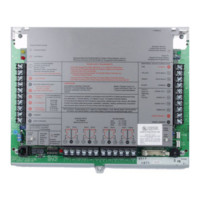
Figure 1: Control Panel Wiring Connections
See Table 1 for terminal descriptions.

Table of Contents

Questions and Answers:

Bosch DS7240V2 Specifications

General IconGeneral
TypeControl Panel
Event LogUp to 1000 events
Power Supply12V DC
Operating Temperature32°F to 120°F (0°C to 49°C)
CompatibilityBosch security systems
Partitions8
CommunicationIP
Battery BackupYes
HumidityUp to 93% non-condensing

Summary

Part I: Introduction

1.0 Documentation Conventions

Explains type styles, notes, cautions, warnings, and other conventions used in the document.

2.0 Specifications

Details the environmental, voltage input, power outputs, and data bus specifications of the control panel.

3.0 Standard Features

Covers standard features like communicator, zones, areas, programmable outputs, users, and keyswitch functionality.

6.0 System Options

Describes available system options including arming devices, data bus devices, RF devices, and programming tools.

7.0 System Batteries

Details the standby battery and RAM backup battery requirements and specifications.

8.0 Available Power

Explains the auxiliary power and alarm power specifications for system devices.

9.0 Installer Keypad Connector

Describes the connector used for installer keypads and programming diagnostics.

Part II: System Installation and Setup

10.0 Control Panel Installation

Covers the physical installation of the control panel, including enclosure mounting and EMI considerations.

11.0 Telephone Connections

Details how to connect the control panel to the incoming telephone line for communication.

12.0 Phone Line Fault

Explains the phone line monitoring circuit and potential issues.

13.0 Communication Failure (Comm Fail)

Describes how the control panel handles communication failures to routing destinations.

14.0 Arming Device Installation

Covers the installation of keypads and other arming devices, including addressing and wiring.

15.0 On-board Sensor Loop Setup

Details the setup of the eight on-board sensor loops, including tamper-wired and no EOL configurations.

16.0 On-board Output Setup

Explains the configuration of the four on-board programmable outputs (PO 1-PO 4).

17.0 RF3227E RF Receiver Setup

Covers the setup, addressing, installation, and programming of the RF receiver.

18.0 Off-board Sensor Loops (DX2010)

Details the overview, installation, wiring, and addressing of the DX2010 input expander.

19.0 Off-board Outputs (DX3010)

Covers the overview, configuration, and relay outputs of the DX3010 Octo-Output Expander.

20.0 RS-232 Serial Interface (DX4010i/DX4010)

Details the overview, installation, configuration, and RPS direct connection for serial interface modules.

21.0 Network Interface Module (DX4020)

Covers the overview, addressing, installation, and wiring of the DX4020 Network Interface Module.

22.0 Door Access Control Module (DACM)

Explains the overview, wiring, and supervision of the Door Access Control Module.

23.0 System Power Up

Describes the system behavior during power up and initial stabilization.

24.0 System Status LED

Details the location and operation of the system status LED.

25.0 Installer Keypad

Explains the requirements for using an installer keypad for programming.

26.0 Installer Mode

Describes how to access and use the installer mode for system configuration.

27.0 Installer Menu

Lists and explains the options available within the installer menu for system testing and programming.

Part III: How to Program

28.0 Keypad Programming

Covers using text keypads for programming and the restrictions on LED keypads.

28.1 Installer Mode/Installer Menu

Details methods to access the control panel's programming mode and installer menu.

28.2 Expert/Installer Programming Modes

Explains the differences between Installer and Expert programming modes.

28.3 Parameter Addresses

Explains how parameters are stored and accessed via addresses and data digits.

28.4 Text Entry Addresses

Describes how to enter text for various programming parameters using keypad keys.

28.5 Exit Programming Mode

Details the procedure for exiting programming mode and system behavior upon exit.

Part IV: Control Panel Programming

29.0 Understanding the Parameter Option Charts

Explains how to interpret charts used for selecting parameter options.

30.0 Routing Destinations

Configures report routing destinations and phone numbers for the control panel.

31.0 Phone, Auto-Forward and RPS Configuration

Sets dialing formats and configures auto-forward and RPS features.

32.0 Global Reporting Options

Configures global reporting options for all areas, zones, and users.

33.0 Tests

Covers automatic test report options and timing configurations.

34.0 Programming Options

Details options for remote programming, including callbacks and session termination.

35.0 Global Open/Close Options

Configures global arming options like Perimeter Only and Answering Machine Bypass.

36.0 Areas

Configures control panel areas, including account numbers and reporting options.

37.0 PIN Configuration, Installer PIN

Sets PIN length and configures the installer PIN and user PINs.

38.0 Users

Details user configuration, including PIN, authority level, and area assignment.

39.0 Keypads

Covers keypad addressing, DACM area options, and supervision.

40.0 Help Function Keys and Duress Parameters

Configures keypad help functions, duress reporting, and alarm responses.

41.0 Locations

Defines location parameters, including device type, zone function, area, and zone number.

42.0 Zone Function Configuration

Determines how the system responds to sensor loop or transmitter changes.

43.0 Global Zone Configuration

Configures global zone response options and bypass/force arm report routing.

44.0 Global Output Configuration

Sets global options for programmable outputs, including siren supervision and arming indications.

45.0 Outputs

Details output configuration parameters for on-board and off-board outputs.

46.0 Skeds

Defines programmable events that occur at specific times and days of the week.

47.0 RF Receiver Configuration

Configures premises RF receiver options, including supervision and keyfob behavior.

48.0 RS-232 Module Configuration

Details output configuration and baud rate options for RS-232 serial interface modules.

49.0 DX8010 Telephone Module Configuration

Covers DX8010 access options for telephone module configuration.

50.0 RF Keypads

Details RF keypad options, addressing, and area assignments.

51.0 RF Keyfobs

Explains RF keyfob management, receiver assignment, and options like panic and arming.

52.0 Tamper Response Configuration

Configures control panel response to tamper alarms and trouble reports.

53.0 Exit Delay Configuration

Sets parameters for exit delay, including contact set and exit terminator options.

54.0 Miscellaneous Programming Options

Covers confirmation alarm timer and factory default settings.

55.0 Reporting Format Configuration

Details various reporting formats like Personal Dialing, BSIA Fast, and Basic Pager.

56.0 Network Communication

Covers configuring the control panel for network communication via Ethernet.

57.0 DACM Configuration

Details the three-step process for configuring DACM modules with the control panel.

58.0 Test the System

Provides guidance on performing a complete functional test of the control panel and its devices.

Part V: Reference Materials

59.0 Troubleshooting

Provides solutions for common problems related to arming, zones, programming, and keypads.

60.0 Data Bus Address Quick Reference

A quick reference table for data bus addresses and their corresponding device descriptions.

61.0 Communication Attempt Tables

Tables detailing communication attempt sequences for different destination and phone/IP configurations.

62.0 History Log

Explains how to view and interpret the control panel's event history log.

63.0 Control Panel Events and Reporting Formats

Lists control panel events, their descriptions, reports, and linked zone types.

64.0 Call for Service Details

Details system conditions that trigger a 'Call for Service' display and their explanations.

65.0 User Keypad Commands

Lists common user keypad commands for system arming, disarming, and other functions.

66.0 Standby Battery Calculation

Provides a guide for calculating standby battery capacity based on system components.

67.0 Glossary

Defines key terms and concepts used throughout the installer's guide.

Related product manuals