DS7200V2-UK Installer's Guide Copyright 2007 Bosch Security Systems, Inc. P/N: 4998152533-02 Page 25
PART II: SYSTEM INSTALLATION AND SETUP
19.6 DX3010 Address Programming
Each DX3010 module connected to the control panel
must have its own address DIP switches set to either
address shown in Table 10. Shaded cells only apply
to the DS7240V2.
Output # Data Bus Address
5 to 12 Data Bus Address 150
13 to 20 Data Bus Address 151
Table 10: DX3010 Addresses
Any time the address DIP switches are
changed, you must cycle the power to the
module OFF and then ON for the changes to
take effect.
Set the address DIP switches as shown in Table 11.
“DN” indicates that the DIP switch is CLOSED
(Down); “UP” indicates that the DIP switch is OPEN
(Up). Shaded cells only apply to the DS7240V2.
DX3013 DIP Switches Data Bus
Address
1 2 4 8 16 MODE
150 UP UP UP UP UP DN
151 DN UP UP UP UP DN
Table 11: DX3013 Address DIP Switch Settings
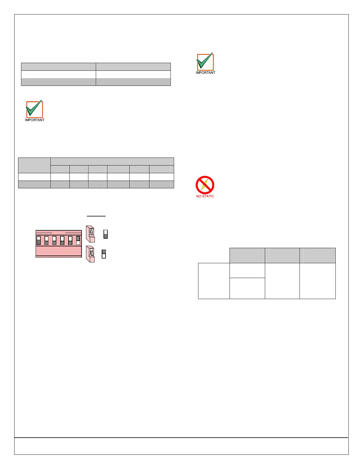
See Figure 35 for DX3010 DIP switch configuration.
Example:
Module Address 150
= Switch OPEN (Up)
=
= Switch CLOSED (Down)
=
OPEN
123456
Figure 35: DX3010 DIP Switch Configuration
19.7 DX3010 Supervision
The control panel supervises proper communication
to the DX3010. If it fails to communicate with the
DX3010, it sends a “Dbus Missing” {125} report.
20.0 RS-232 Serial Interface
(DX4010i/DX4010)
There are some PCB layout differences
between the DX4010i and the DX4010.
However, the two modules wire, program,
and operate the same. The figures in this
section show the DX4010i’s PCB.
20.1 DX4010i/DX4010 Overview
Both modules are RS-232 serial interface modules
that connect a standard serial printer, or other serial
device, to the control panel. They can also be used to
create a direct connection for on-site programming
using RPS. The DX4010i is a DTE serial interface
module.
Depending on which module you have, see the
DX4010i Installation Guide (P/N: 4998141106) or the
DX4010 Installation Guide (P/N: 49539) for complete
instructions.
20.2 DX4010i/DX4010 Installation
Both modules contain static-sensitive
components and must be handled with care.
Follow anti-static procedures when handling
either module.
Both modules are shipped in a plastic enclosure that
can be placed on a desktop or similar surface.
Distance from the control panel is determined by the
total combined wire length of all devices (including
keypads) connected to the control panel’s data bus
terminals.
Power
Source
0.8 mm
(#22 AWG)
1.2 mm
(#18 AWG)
Control
Panel
DX4010i/
DX4010
to Control
Panel
External
Power
Supply
305 m
(1007.7 ft.)
610 m
(2001 ft.)
Table 12: DX4010i/DX4010 Wire Lengths