9Bosch | 09/04 | 74-06200-000-F
D2071A | Operations & Installation Guide | 2.0 Installation
1. Do not connect earth ground when connected to a 24 VDC power supply.
2. Do not connect a battery when connected to a 24 VDC power supply (maximum charging current of
300 mA).
1
8
5
7
4
10
11
2
6
9
3
1
2
3
4
5
6
7
8
11
18
17
16
15
14
13
10
9
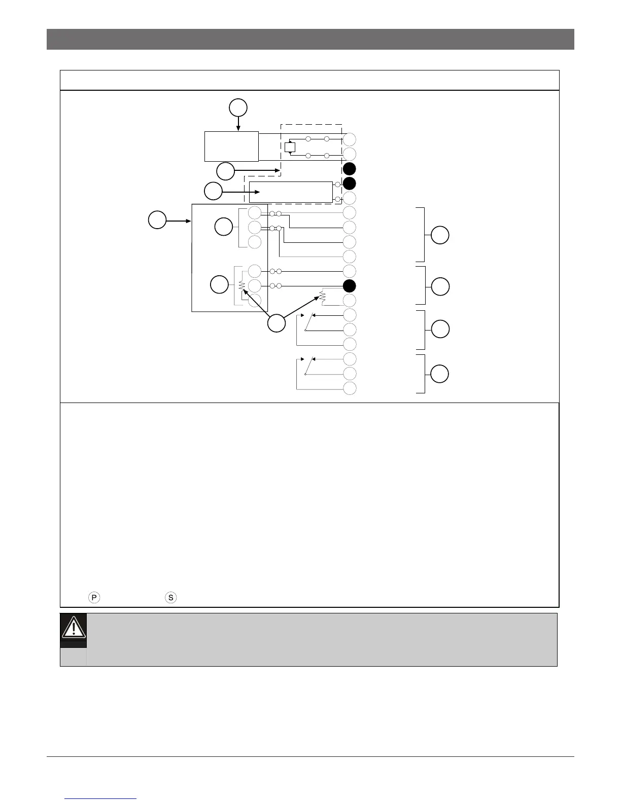
12 VAC, 20 VA, 60 Hz, OR + 24 VDC
ALARM RELAY NO
ALARM RELAY COM
ALARM RELAY NC
TBL RELAY NO
TBL RELAY COM
TBL RELAY NC
SUPERVISORY LO
SUPERVISORY HI
INITIATING B2 +
INITIATING B1 +
INITIATING A2 –
INITIATING A1 –
BATTERY +
BATTERY –
EARTH GND
12 VAC, 20 VA, 60 Hz, OR – 24 VDC
C
NC
NO
C
NC
NO
-
+
N
C
N
N
C
N
PS
PS
P S
P
P
P S
-
+
P S
12
SUPERVISORY HI
P S
1 - Primary power supply (24 VDC supply from UL Listed FACP or 12 VAC, 20 VA transformer)
2 - Alternate power supply
3 - D126 Battery (12 V, 7 Ah) or D1219 Battery (12 V, 2.3 Ah)
4 - Alarm initiating circuit (Trouble = open on Terminals 6, 7, 8, and 9; Alarm = short from Terminals 6 and 7 to
Terminals 8 and 9)
5 - Dry Closure Alarm Indicator Relay (Form “A” Normally Open)
6 - FACP
7 - Supervisory circuits: Mode 3 (Alarm [short] = 0 VDC to 1.7 VDC; Normal [resistive] = 1.9 VDC to 5.8 VDC;
Trouble [open] = 6.0 VDC to 10.2 VDC)
8 - Dry Closure Trouble Indicator Relay (Form “A” Normally Open)
9 - 1.8 k
Ω
EOL resistor
10 - Phone Trouble Relay (maximum rating 2 A at 30 VDC)
11 - Initiating Circuit Alarm Relay (maximum rating 2A at 30 VDC)
Note: = Power limited; = Supervised
Figure 3: Slave Communicator Installation