D7050/D7050TH | Installation Instructions | 4.0 Setting the Address
4 Bosch Security Systems, Inc. | 9/06 | 47458E
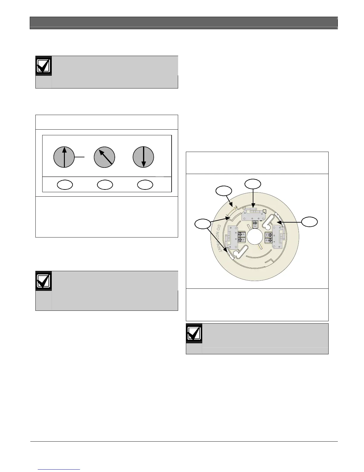
4.0 Setting the Address
Set the D7050’s address before
connecting to the control panel and
applying power. The address number is the
same as the input point or zone number.
Set the D7050’s address using a flat-blade screwdriver
to position the rotary switches (Figure 3) located on the
front. Note that the switches click when turned.
Figure 3: Setting the D7050 Address
2
0
7
6
3
9
5
4
1
2
8
0
7
6
3
9
5
4
1
2
8
0
0
1
1
2
A
B
321
1 - Hundreds 2 - Tens 3 - Ones
A = D7024 FACP, B = DS9400M FACP
For example:
0 hundreds, 9 tens, 5 ones = Address 95 on the
D7024 FACP
The valid address range is from 009 to 255. Refer to
the D7024 Operation and Installation Guide (P/N: 31499)
or the DS9400M Reference Guide (P/N: 44578) for
additional address limitations.
The A address range works on the D7039
Multiplex Expansion Module with the
D7024 FACP. The B address range works
on the DS9431 Multiplex Expansion
Module with the DS9400M FACP.
Figure 3 shows the A address range set at 095, allowing
the D7039 to work with the D7024 FACP.
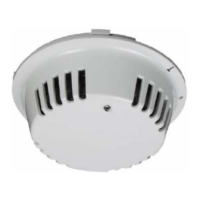
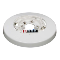
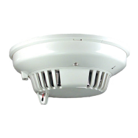
5.0 Mounting
1. Unscrew the tamper screw located in the recess on
top of the dust cover.
2. Remove the dust cover from the detector. You can
replace the dust cover during construction periods,
but it must be removed once the alarm system is
enabled.
3. Mount and wire the base according to its
instructions.
4. Mount the detector on the base, turning it
clockwise until it clicks into place. When secure,
the alignment line aligns with the tamper screw
hole (refer to Figure 4).
Figure 4: Mounting D7050/D7050TH on the
Base
+1
R2
3-
1
2
3
3
1 - Base contacts (3)
2 - Alignment arrow
3 - Insert detector contacts here and rotate
clockwise
The detector is keyed. Do not force the
detector onto the base.