D7050/D7050TH | Installation Instructions | 9.0 Specifications
.
Bosch Security Systems, Inc. | 9/06 | 47458E 7
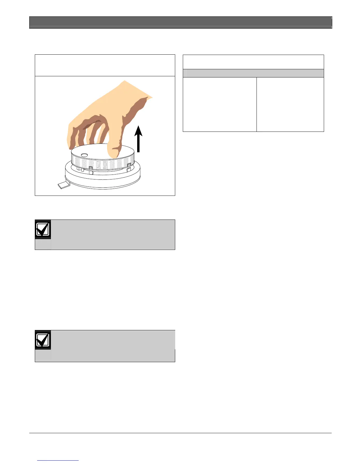
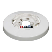
4 Gently pull the cover up and away from the
chamber as shown in Figure 6.
Figure 6: Removing the D7050/D7050TH
Chamber Cover
5 With the chamber cover removed, clean the inside
of the cover with a vacuum or clean dry
compressed air.
Do not clean the D7050/D7050TH
components with water or any liquid
cleaner.
6 Replace the chamber cover ensuring the holes for
the LED and thermistor line up over the LED and
thermistor. Place the cover parallel to the chamber
and gently snap the locking tabs into place.
7 Replace the detector cover and carefully align the
LED and thermistor holes.
8 Return the detector to its base.
9 Test the detectors for proper calibration using one
of the tests described in Section 7.0 Testing
beginning on page 5.
Do not paint the D7050/D750THs. Paint or
other foreign matter covering the screens
can stop or delay smoke from entering the
detector.
9.0 Specifications
Table 1: Specifications
Standby Current
Alarm Current
Minimum Operating Voltage
Power-up Time
Installation Temperature
Relative Humidity
Required Accessories
0.5 mA at 12 VDC
0.56 mA at 12 VDC
8 VDC peak
22 sec maximum
+32°F to 100°F
(0°C to +38°C)
0% to 93% non-condensing
D7050-B6 Detector Base