Page 2 © 2004 Bosch Security Systems DS860 Series Installation Instructions
On
Off
INT
STD
• Route wiring as necessary. Route to the rear of the base and
through the wire entrance. Make sure all wiring is unpowered
before routing.
• Securely attach the base to the mounting surface.
• Return the circuit board to the base and tighten the Vertical
Adjust Screw.
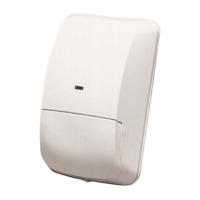
4.0 Wiring
CAUTION
Only apply power after all connections have been
made and inspected. Do not coil excess wiring
inside detector.
NOTE: Input power must use only an Approved Limited Power
Source. Alarm and Tamper Contacts to be connected to a
SELV (Safety Extra-Low Voltage) circuit only.
9-15 VDC
Input
–
+CNC
Alarm
Relay
SP T SPT
Tampe r
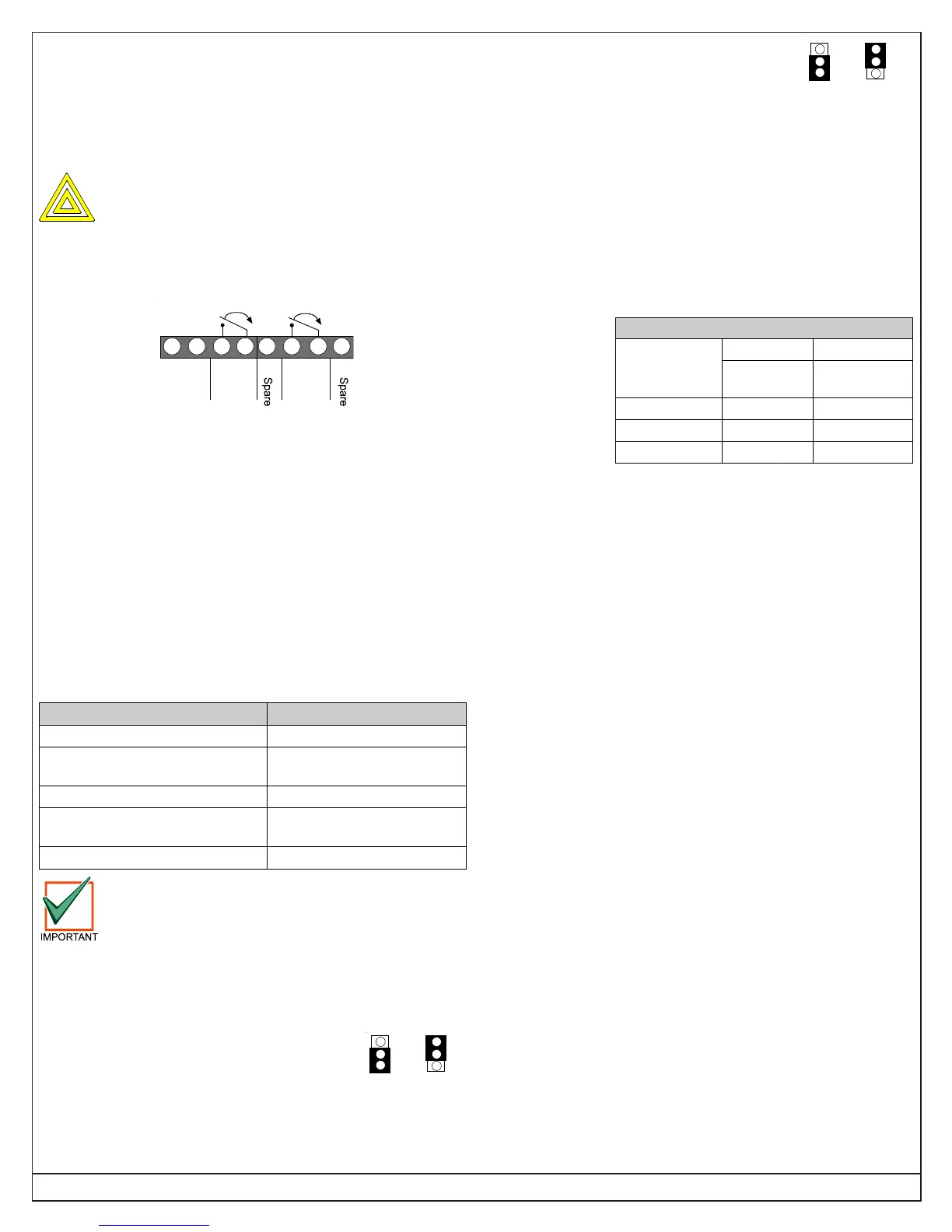
1234
Alarm
5678
Tamper
• Terminals 1 (–) & 2 (+): Voltage limits are 9 to 15 VDC. Use no
smaller than #22 AWG (0.8 mm) wire pair between the detector
and the power source.
• Terminals 3 & 4: Alarm relay (reed) contacts rated 3 watts,
125 mA, 28 VDC maximum for DC resistive loads and
protected by a 4.7 ohm, 0.5 watt resistor.
NOTE: Do not use with capacitive or inductive loads.
• Terminals 5 and 8: Spare.
• Terminals 6 & 7: Tamper contacts rated at 28 VDC, 125 mA.
NOTE: Plug the wire entrance hole with the foam plug provided
after all wiring connections have been made.
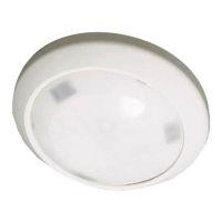
5.0 LED Operation
The detector uses a tri-color LED to indicate the various alarm and
supervision trouble conditions that may exist. See chart below.
LED Cause
Steady red Unit alarm
Steady yellow
Microwave activation
(walk test)
Steady green PIR activation (walk test)
Flashing red
Warm-up period
after power-up
Flashing red (4 pulse sequence) Replace Unit
If the detector experiences a Microwave or PIR
self-test failure, it is in need of replacement.
NOTE: During walk testing, the LED will light for the first
technology (microwave or PIR) and then light red to
indicate a detector alarm. The LED will not indicate
activation of the second technology by lighting its color.
6.0 Feature Selection
6.1 LED On/Off Pins
The ON position allows operation of the tri-color LED. If LED
indication is not desired after setup and walk tests are completed,
place in the OFF position. The OFF position does not prevent the
LED from indicating supervision trouble conditions.
6.2 PIR Sensitivity Selection Pins
For selection, place the plug across the pins
marked STD for Standard or INT for
Intermediate mode.
• Standard Sensitivity: The recommended setting for maximum
false alarm immunity. Tolerates environmental extremes on
this setting.
• Intermediate Sensitivity: The recommended setting for any
location where an intruder is expected to cover only a small
portion of the protected area. Tolerates normal environments
on this setting. This setting will improve your intruder catch
performance.
7.0 Set-up and Walk Tests
Select the vertical starting angle from this chart:
To adjust the
vertical starting
angle for the
desired
mounting height
and range,
loosen the
vertical adjust
screw and slide
the board up, to
point the angle down. Note the settings on the vertical adjust scale.
• Place the LED plug in the ON position and replace the cover.
7.1 Establishing PIR Pattern Coverage
• Turn the Microwave range adjust to minimum.
• Replace the cover and snap it into place. This will close the
tamper switch.
• Wait two minutes minimum after applying power to start walk
tests.
NOTE: During the warm-up period, the tri-color LED will flash red
until the unit has stabilized (approximately 1 to 2 minutes)
and has seen no movement for two seconds. When the
tri-color LED stops flashing, the detector is ready to be
tested. With no motion in the protection area, the tri-color
LED should be OFF. If the LED is on, re-check the
protection area for disturbances affecting the microwave
or PIR technologies.
• Walk test across the pattern at its farthest edge, then several
times closer to the detector. Start walking from outside of the
intended protection area, and observe the tri-color LED. The
edge of the pattern is determined by the first green, PIR
activation of the LED (or the first red activation if the yellow
microwave LED activates first).
• Walk test from the opposite direction to determine both
boundaries. The center of the pattern should be pointed
toward the center of the intended protection area.
NOTE: The pattern may be moved ±10° horizontally by rotating the
lens window left or right.
• Slowly bring your arm up and into the pattern to mark the lower
boundary on PIR alarm. Perform this task at 10 to 20 ft. (3 to 6
m) from the unit. Repeat from above for the upper boundary.
The center of the pattern should not be tilted upward.
DS860
Broad Long Range
Mounting
Height
60 ft.
(18 m)
100 ft.
(30 m)
6.5 ft. (2 m) -4° -2°
7.5 ft. (2.3 m) -5° -3°
8.0 ft. (2.4 m) -6° -3°
 Loading...