DS860 Series Installation Instructions © 2004 Bosch Security Systems Page 3
NOTE: If desired coverage cannot be achieved, try angling the
coverage pattern up or down to assure the pattern is not
aimed too high or low. The angle of the PIR pattern may be
vertically positioned between -10° and +2° by loosening
the Vertical Adjust screw and sliding the circuit board up or
down. Moving the board up will angle the pattern
downward.
• Tighten the screw snug when positioning is completed.
7.2 Establishing Microwave Coverage
NOTE: It is important to wait one minute after removing/replacing
the cover so the microwave portion of the detector can
settle, and to wait at least ten seconds between the
following walk testing procedures.
• The tri-color LED should be OFF before walk testing.
• Walk test across the pattern at the intended coverage’s
farthest end. Start walking from outside the intended
protection area and observe the tri-color LED. The edge of the
microwave pattern is determined by the first yellow, microwave
activation of the LED (or the first red activation if the green PIR
LED activates first).
• If adequate range can not be reached, increase the Microwave
Range Adjust slightly. Continue walk testing (waiting one
minute after removing/replacing the cover) and adjusting the
range until the farthest edge of desired coverage has been
accurately placed.
NOTE: Do not adjust the microwave range higher than required.
Doing so will enable the detector to catch movement
outside of the intended coverage pattern.
• Walk test the unit from all directions to determine all the
Microwave pattern boundaries. Wait at least ten seconds
between walk tests.
7.3 Establishing Detector Coverage
• The tri-color LED should be OFF before walk testing.
• Walk test the unit from all directions to determine the detection
boundaries. A detector alarm is signaled by the first red
activation of the tri-color LED after an initial green or yellow
activation.
8.0 Supervision Features
The supervision features function as follows:
• PIR/Microwave: The complete circuit operation of these
subsystems is checked approximately every 24 hours. If the
PIR or MW subsystem fails, the tri-color LED will flash red 4
times per cycle and the unit should be replaced.
• Default: If the microwave subsystem fails, the detector will
default to PIR technology protection. The PIR signal sensitivity
will automatically change from INT to STD.
9.0 Maintenance
At least once a year, the range and coverage should be verified. To
ensure continual daily operation, the end user should be instructed
to walk through the far end of the coverage pattern. This ensures
an alarm output prior to arming the system.
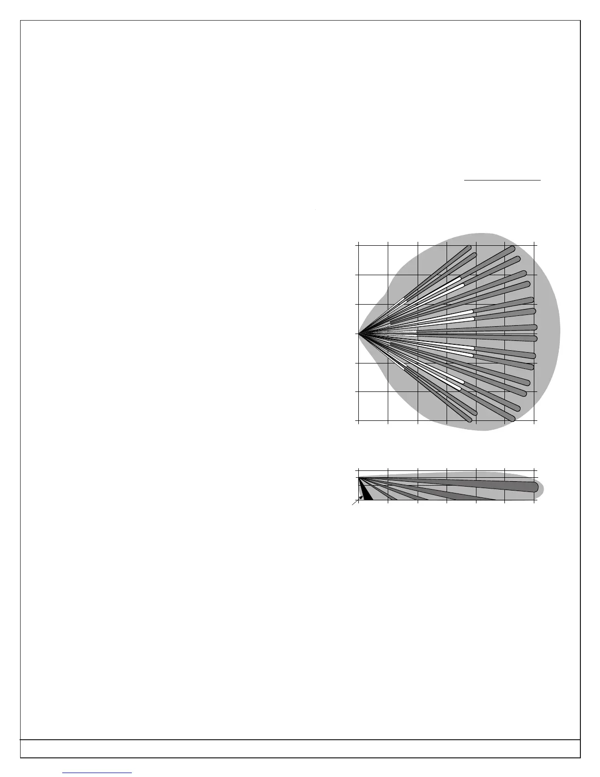
10.0 Coverage Patterns
The DS860 has a standard broad coverage pattern or an optional
long-range coverage pattern. The protected coverage area is where
the microwave and PIR patterns overlap.
An optional Look Down lens is located under the detector. This
lens must be unmasked before it is operational. Use caution to
remove the black mask only. Do not attempt to remove the white
lens assembly. The Look Down lens is
not recommended for
installations containing pets or small animals. The Look Down
zone is shown in black on the Coverage Pattern drawings.
Standard Broad Coverage
0 102030405060
Feet
0369121518
Meters
10 ft.
0 ft.
-5°
SIDE VIEW
A-I
J-M
N-P
Q, R
3 Meters
7.5 ft.
2.3 m
0369121518Meters
0 102030405060Feet
0 Feet
10
20
30
10
20
30
3
6
9
3
6
9
TOP VIEW
B
A
C
D
G
H
I
J
K
L
M
N
O
P
E
F
R
Q
0Meters
Look-Down
 Loading...