EasyManua.ls Logo

Bosch DS937 User Manual

Bosch DS937
2 pages
To Next Page IconTo Next Page
Page #1 background imageLoading...
Page #1 background image
4.4
Installation Guide for DS937
Ceiling Mounted, Passive Infrared (PIR)
Intrusion Detectors
1.0 Description
The DS937 is a low-profile, ceiling-mount Passive Infrared Intrusion detector that provides a 360° coverage pattern. The low profile
design provides a recessed-mount look, even when surface mounted. It is easy to install with access to wiring and programming options
available without removing the detector from the ceiling. With a 50 ft. (14 m) diameter coverage pattern, it is an ideal choice for applications
that require ceiling mounting and spot or 360° detection.
2.0 Specifications
Input Power: 9 to 30 VDC; 7.5 to 24 VAC.
Current Draw: 17 mA maximum at 12 VDC.
Standby Current: Intended for connection to DC power
supplies capable of supplying power if
primary power fails.
Coverage: 50 detection zones.
Detectable Speed: 0.5 to 15 ft./s (0.2 to 5.0 m/s)
Alarm Contacts: NC (Normally Closed) dry contacts, rated
500 mA, 10 W max. @ 30 VDC.
Tamper Switch: NC Integral, Cover-Activated
Sensitivity Selection: Field selectable for 1, 2, 3, or 4 pulse
counts.
Storage and +14°F to +122°F (-10°C to +50°C).
Operating
Temperature:
Humidity: 0 to 95% non-condensing
Dimensions: 5 inches diameter by 1.5 inches high
(125 mm diameter x 38 mm high)
3.0 Avoid:
4.0 Mounting
4.1 Use the mounting template to position and drill the wiring
hole and starter holes for the two mounting screws provided with
the detector.
4.2 Install the provided mounting screws leaving enough
space between the screwhead and the mounting surface to
allow placement of the detector base.
Mounting Height
Detection Area
Maximum Diamete
r
8 ft. (2.4 m)
10 ft. (3.0 m)
12 ft. (3.7 m)
38 ft. (11.6 m)
46 ft. (14.0 m)
50 ft. (15.2 m)
Only apply power
after all connections
have been made and
inspected.
Connect wires to the
Terminal Block by passing
them through the Wiring
Passage.
Alarm Output
(Normally Closed)
Tamper Switch
(Normally Closed)
Alarm Memory
First To Latch
Power Input
(nonpolar)
1. Remove the Outer Cover Ring (may be pried
loose with a small flatbladed screwdriver).
2. Loosen the cover screw.
3. Turn the cover dome counterclockwise and lift
it off the detector.
4.3 Mount the detector base
4. Slide the detector over the mounting
screws.
5. Rotate the detector clockwise until the slots
firmly engage the mounting screws.
6. Tighten the mounting screws.
Mounting
Outdoors
Moving
Objects
Pets and
Small Animals
Direct Hot or
Cold Drafts
Heat Sources
Windows and
Uninsulated Walls
Air Conditioning
Outlets
Water or
Oil Vapor
Direct Exposure
to Sunlight
1. Pry here if
necessary
2. Loosen
Cover Screw
3. Rotate Cover
to unlock
Mounting Holes
Question and Answer IconNeed help?

Do you have a question about the Bosch DS937 and is the answer not in the manual?

Bosch DS937 Specifications

General IconGeneral
CommunicationWired
Power Supply9-15 VDC
Temperature Range-10°C to +50°C
Alarm RelayNormally closed (NC)
Tamper RelayNormally closed (NC)

Summary

Product Description

Technical Specifications

Input Power

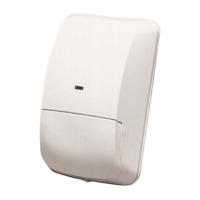
Specifies the required input voltage and current range for the detector.

Current Draw

Details the maximum current consumption at 12 VDC.

Standby Current

Describes the current draw for DC power supplies during standby.

Coverage Details

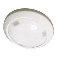
Details the detection zones and coverage patterns based on mounting height.

Detectable Speed

Specifies the range of detectable object speeds for alarm activation.

Alarm Contacts

Defines the specifications for the NC alarm contacts.

Tamper Switch

Notes the tamper switch type and activation.

Sensitivity Selection

Indicates field selectable pulse counts for sensitivity.

Operating Environment

Specifies the operating temperature and humidity limits.

Physical Dimensions

Provides the physical dimensions of the detector.

Installation Avoidances

Mounting Procedures

Template and Hole Drilling

Instructions for using the template to drill holes for mounting.

Mounting Screw Installation

Guidance on installing mounting screws for base attachment.

Detector Base Mounting

Step-by-step instructions for physically mounting the detector base.

Terminal Block Wiring

Procedure for connecting wires to the terminal block for detector operation.

Wiring and Settings

Alarm Memory and First To Latch Wiring

Instructions for configuring Alarm Memory and First To Latch functions.

LED On/Off Select Switch

Configuration for the LED On/Off Select Switch.

Sensitivity Switch Settings

Guidance on setting pulse count and detection range.

Masking Unwanted Zones

Procedure for masking unwanted detection zones.

Detector Reassembly

Steps for reassembling the detector after adjustments.

Walk Test and Coverage Patterns

Walk Test Procedure

Instructions for performing a walk test to verify coverage.

Coverage Patterns

Visual representation of detection coverage patterns.

Related product manuals