EasyManua.ls Logo

Bosch DS860 Series User Manual

Bosch DS860 Series
4 pages
To Next Page IconTo Next Page
Page #1 background imageLoading...
Page #1 background image
Installation Instructions
for the DS860 Series
TriTech Microwave/PIR Intrusion Detectors
1.0 Specifications
Dimensions (HxWxD): 5 in. x 2.8 in. x 2.2 in.
(12.7 cm x 7.1 cm x 5.6 cm)
Input Power: 9 to 15 VDC, 16 mA DC nominal
(up to 48 mA DC during walk testing or
trouble conditions). Useonly an
Approved Limited Power Source.
Standby Power: No internal standby battery.
Standby power must be provided by
an Approved Limited Power Source.
Sixteen mAh required for each hour of
standby time needed.
For UL Listed
Requirements, four hours (64 mAh)
minimum are required.
Alarm Relay: Silent operating Normally Closed
reed relay. Contacts rated 3 watts,
125 mA, 28 VDC maximum for DC
resistive loads; and protected by a
4.7 ohm, 0.5 watt resistor in the
common "C" leg of the relay. To be
connected to a SELV (Safety Extra-Low
Voltage) circuit only. Do not use with
capacitive or inductive loads.
Temperature Range: -40°F to +120°F (-40°C to +49°C).
For UL Listed Requirements, the
temperature range is +32°F to +120°F
(0°C to +49°C).
Microwave Frequency:
DS860: 10.525 GHz (UL Listed)
DS860A: 10.687 GHz (Export only, not UL
Listed)
DS860B: 9.9 GHz (Export only, not UL Listed))
Coverage:
Broad (standard): 60 ft. by 60 ft. (18 m by 18 m)
Long Range (optional): 100 ft. by 10 ft. (30 m by 3 m)
Internal Pointability: +2° to –10° Vertical, ±10° Horizontal.
Tamper: Normally Closed (with cover on).
Contacts rated at 28 VDC, 125 mA
max. To be connected to a SELV
(Safety Extra-Low Voltage) circuit
only. Connect tamper circuit to 24-hour
protection circuit.
Options: B328 Gimbal Mount Bracket, B335
Low Profile Swivel Mount Bracket,
B338 Ceiling Mount Bracket, OLR92
Long Range Barrier Lens
NOTE: Use of a bracket may reduce range and increase dead
zone areas.
U.S. Patent Numbers: Protected under one or more of the
following U.S. Patent Numbers: #4,660,024, #4,764,755,
#5,077,548, #5,208,567, #5,262,783, and #5,450,062. Other
patents pending.
Compliance: This device complies with Part 15 of the FCC
Rules and with RSS-210 of Industry and Science Canada.
Operation is subject to the following two conditions:
(1) this device may not cause harmful interference, and
(2) this device must accept any interference received,
including interference that may cause undesirable
operation.
Changes or modifications not expressly approved by Bosch
Security Systems can void the user’s authority to operate the
equipment.
2.0 Installation Considerations
NOTE: The DS860 is not recommended for installations
containing pets or small animals. Use the DS820 or
DS835 for such installations.
Never install the detector in an environment that causes an
alarm condition in one technology. Good installations start with
the LED OFF when there is no target motion. It should never be
left to operate with the tri-color LED in a constant or intermittent
green, yellow, or red condition.
Point the unit away from outside traffic (roads/alleys).
NOTE: Microwave energy will pass through glass and most
common non-metallic construction walls.
Avoid installations where rotating machines (e.g. ceiling fans)
are normally in operation within the coverage pattern. Point the
unit away from glass exposed to the outdoors and objects that
may change temperature rapidly.
NOTE: The PIR detector will react to objects rapidly changing
temperature within its field-of-view.
Eliminate interference from nearby outside sources.
3.0 Mounting
Select a location likely to intercept an intruder moving across
the coverage pattern. The surface should be solid and
vibration-free. Mounting height range is 6 to 8 ft. (1.8 to
2.4 m). Recommended mounting height is 7.5 ft. (2.3 m).
Remove the cover. Insert a flathead screwdriver into the locking
tab hole at the bottom front of the detector. Pull the cover up
and forward.
Vertical
Adjust
Screw
Tri-color
LED
Ter min al
Strip
LED
On/Off
Pins
MW
- 4°
- 8°
On
Off
Microwave
Range Adjust
PIR
Sensitivity
Selection Pins
Vertical Adjust
Scale
Look Down Lens
MIN MAX
Face of Lens
(masking area)
Corner Mount
Knockout (4)
Surface Mount
Knockout (2)
Wire
Entrances
Bracket Mount
Knockout
Vertical Adjust
Screw Mount
Cover Tab and
Locking Screw Hole
Wire
Entrances
Remove the circuit board from the base. Loosen the Vertical
Adjust Screw and slide the circuit board down, then out.
Break away the appropriate thin-wall wire entrance and
mounting hole coverings in the base.
Using the base as a template and aligning it so that the
detector will be mounted with the terminal block at the top and
the PIR lens at the bottom, mark the location of the mounting
holes on the mounting surface. Pre-start the mounting screws.
Question and Answer IconNeed help?

Do you have a question about the Bosch DS860 Series and is the answer not in the manual?

Bosch DS860 Series Specifications

General IconGeneral
Coverage Area50 ft x 50 ft (15 m x 15 m)
Tamper SwitchYes
Walk TestYes
Power Requirements12 VDC
TypeMotion Detector
Power Supply12 VDC

Summary

Specifications

Installation Considerations

Pets or Small Animals Recommendation

DS860 not recommended for installations with pets or small animals; use DS820 or DS835 instead.

Environmental Considerations

Avoid environments causing false alarms, ensure LED is OFF during no motion, point away from traffic.

Microwave Energy Propagation

Microwave energy passes through glass and non-metallic walls; avoid rotating machines and rapid temperature changes.

PIR Detector Behavior

PIR detector reacts to rapidly changing temperature within its field-of-view; eliminate nearby interference.

Mounting

Mounting Location and Height

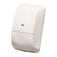
Select location to intercept intruders; surface should be solid. Mounting height 6-8 ft (1.8-2.4 m).

Cover Removal Procedure

Remove cover by inserting screwdriver into locking tab hole at the bottom front and pulling cover up/forward.

Circuit Board Removal

Remove circuit board by loosening Vertical Adjust Screw and sliding board down, then out.

Base Preparation

Break away thin-wall wire entrance and mounting hole coverings in the base as needed.

Marking Mounting Holes

Use base as template, aligning terminal block at top, PIR lens at bottom. Mark mounting holes, pre-start screws.

Wiring

Power and Circuit Connections

Input power 9-15 VDC, alarm/tamper contacts to SELV circuits only. Use Approved Limited Power Source.

Alarm Relay Wiring

Connect alarm relay (terminals 3 & 4) to DC resistive loads. Do not use with capacitive or inductive loads.

Tamper Contact Wiring

Connect tamper contacts (terminals 6 & 7) to a 24-hour protection circuit.

LED Operation

LED Status Indicators

Tri-color LED indicates unit alarm, microwave, PIR activation, or warm-up status.

LED On/Off Feature

Control LED operation via pins; OFF position disables indication except for supervision trouble.

Feature Selection

PIR Sensitivity Settings

Select STD for maximum false alarm immunity or INT for improved intruder catch performance.

Set-up and Walk Tests

Vertical Angle Adjustment

Adjust vertical angle using chart for desired mounting height and range by sliding circuit board.

Establishing PIR Pattern Coverage

Walk test PIR pattern boundaries; LED should be OFF with no motion. Adjust range and angle as needed.

Establishing Microwave Coverage

Microwave Walk Test Procedure

Walk test microwave pattern boundaries; LED should be OFF. Adjust range slightly to achieve desired coverage.

Establishing Detector Coverage

Detector Walk Test

Walk test detector coverage from all directions. Alarm signaled by first red LED activation.

Supervision Features

PIR/Microwave Subsystem Check

Subsystems checked approx. every 24 hours. Red LED (4 pulses) indicates failure, requires replacement.

Microwave Subsystem Failure

If microwave subsystem fails, detector defaults to PIR technology; PIR sensitivity changes to STD.

Coverage Patterns

Standard Broad Coverage

Illustrates standard broad coverage patterns (Top and Side View) for DS860.

Optional Long Range Coverage

Illustrates optional long-range coverage patterns (Top and Side View) for DS860.

Look Down Lens

Optional Look Down lens available, unmask black mask only. Not recommended for installations with pets.

Pattern Masking

PIR Pattern Masking

Mask PIR coverage pattern using tape on lens (grooved side) to cover specific areas.

Masking Limitations

Masking only eliminates PIR portion of coverage; has no effect on the microwave pattern.

Related product manuals