6720821559 (2017/06)EasyControl Adapter OT-iRT/On-Off
Installation | 17
To dispose of old electrical or electronic devices, you should
use the return and collection systems put in place in the country
concerned.
4 Installation
4.1 Inspection beforehand
▶ Before installation, check that the combination of the
thermostat, the EasyControl adaptor and the boiler is
possible.
The minimum requirements for installation of this product are:
• 2-wire cable with the boiler that is suitable for the use of the
EasyControl adaptor.
4.2 Installation
▶ Ensure that the cable length between the EasyControl
adaptor and the boiler is max. 3 metres, since long data
cables can cause faults.
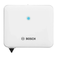
▶ Open the EasyControl adaptor casing ( fig. 3).
▶ Mark the bore holes by hand at the centre- to centre
distance between the slotted holes.
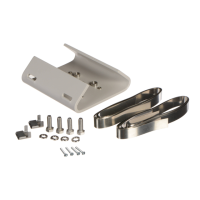
▶ Install the product using the provided screws and rawl
plugs.
▶ Tighten the screws finger-tight.
4.3 Electrical Connection
See the installation instructions for the boiler for more
information on connecting the thermostat.
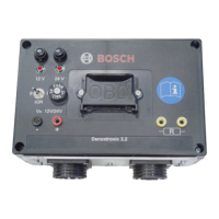
Thermostat and boiler connection
The “thermostat” and “boiler” cable clamps are not polarity
sensitive.
▶ Remove the boiler plug from the socket.
▶ Disconnect the thermostat.
▶ Cut the 2-wire cable between the boiler and the
thermostat.
▶ Connect the part of the 2-wire cable that connects to the
boiler to the “boiler” cable clamps.
▶ Connect the part of the 2-wire cable that connects to the
thermostat to the “thermostat” cable clamps.
Bus connection
The bus is connected in the following way ( fig. 4):
[1] base plate
[2] thermostat or EMS module(s)
[3] EasyControl adaptor
[4] boiler
[5] boiler 2-wire cable
[6] power adaptor
[7] thermostat 2-wire cable
Zero volt contact
An on-off switching unit can be connected through the zero volt
contact ( fig. 5):
[1] normally open connection (NO)
[2] normally closed connection (NC)
[3] common (C)
The default connection is C-NO. Following a heat demand, the
NO contact closes.
▶ Close the EasyControl adaptor casing ( fig. 6).
▶ Connect the power adaptor to the EasyControl adaptor.
5 Commissioning
▶ Position the thermostat.
▶ Insert the power adaptor into a socket.
▶ Insert the boiler plug into a socket.
▶Turn on the boiler.
The EasyControl adaptor will start initialising ( fig. 7).
The steps in table 1 are run through automatically.
# LED indication The EasyControl adaptor:
1 Flashing red … is receiving power and is waiting
for protocol detection.
2 Flashing blue … is processing protocol detection.
3 Constantly blue … has detected a supported protocol
and is initialising the internal
database.
4 Constantly green … has received data from the boiler
as well as from the thermostat.
5 Constantly red … has detected an error during
communication.
6 Dimmed green … is in operation.
Table 1 LED indication during initialisation